1. Motivation and Objectives
As the world shifts to greater reliance on sustainable energy sources, the design and optimization of relevant turbomachinery devices are imperative. The CFturbo software allows its users to build and optimize all components of Hydro Turbines, as shown in this introductory case study of a Francis turbine.
The Francis turbine is a longstanding monument in the world of turbomachinery, dating back to the mid-19th century. Today, Francis turbines are globally the most widely used turbines for hydroelectric power generation.
2. Conceptual Design
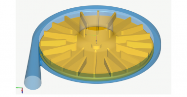
The Francis turbine was invented in the mid-19th century by engineer James Bichens Francis to produce hydroelectric power. Water enters the volute inlet and passes the blade rows of stay vanes and wicket gate before colliding with the runner blades. Then after transmitting its energy, the fluid exits in the axial direction into the draft tube. To extract the maximum amount of power, the shaping of the inlet volute, guide vanes, and runner blades must be carefully designed to allow the water to pass smoothly through the device. Low upstream head losses and the downstream reduction of swirl are imperative and should focus on optimization.
3. Baseline Design
A baseline geometry was prepared using the Hydro Turbine module within the CFturbo software. The initial design point was defined by a volumetric flow rate of 3.89 cubic meters per second, a net head of 26 meters, and a rotational speed of 600 revolutions per minute. An inlet temperature of 20 ̊C and an inlet pressure of 4 bar were also defined. The meridional view is shown below, Fig.1.
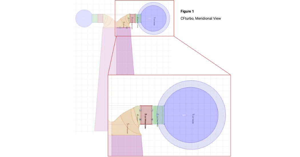
Figure 1 CFturbo, Meridional View
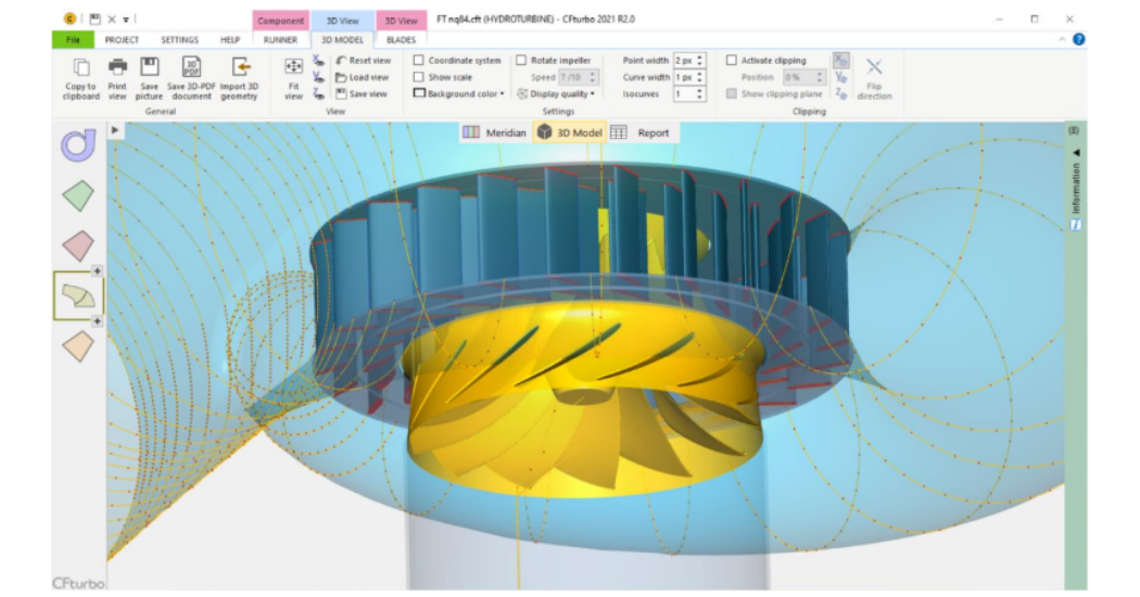
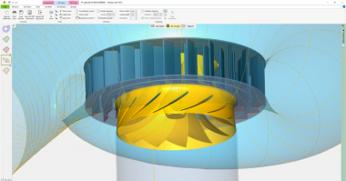
Figure 2 Francis Turbine Design – CFturbo, 3D View
4. Design Exploration using Star-CCM+
To optimize the Francis Turbine base geometry, three design parameters were strategically varied with hopes of analyzing variable sensitivity in performance: 1. the blade position (angle) of the wicket gate, 2. the blade angle at the leading edge of the runner, and 3. the blade angle of the trailing edge of the runner.
Using a CFturbo engineered Python script solution in conjunction with the Replace Part Operation within Star-CCM+, 25 unique Francis Turbine CFturbo designs were created and simulated using a mesh of approximately 8.5 million polyhedral cells and a steady-state solver. Figure # shows the Star-CCM+ mesh of the best design out of the 25.
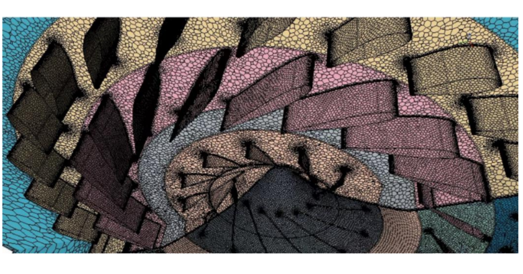
Figure 3 Star CCM+ Polyhedral Mesh
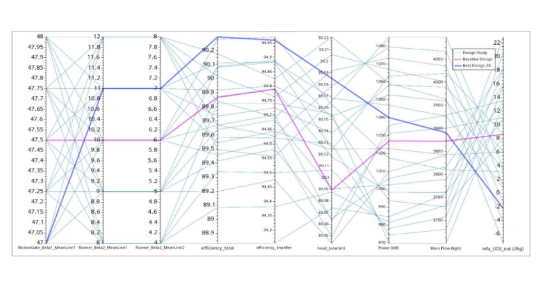
Figure 4 Design Variation Parallel Plot
Figure 4 is a parallel plot displaying the design parameter values as well as significant quantities of interest. The baseline design is displayed in pink. Various result variables were analyzed to evaluate the optimum design. Viable designs were chosen by ensuring the outlet mass flow rate approximately matched the original design point. Next, both the total efficiencies and the runner efficiencies were analyzed.
Finally, the products of the outlet peripheral speed and the outlet absolute circumferential velocity were analyzed to minimize downstream swirl. Given these criteria, “design 20” (displayed in blue) was selected as the best design; at approximately the same outlet mass flow rate, the total efficiency increased from 89.9 % to 90.3 %, and the runner efficiency increased from 94.8% to 95.0%.
Although these improvements seem relatively minuscule, it’s important to highlight that these changes have significant consequences due to the immense scale of Francis turbines. Overall, designs with lower wicked gate angles lead to a decrease in downstream swirl and improved efficiencies. In contrast, models with relatively lower runner blade angles resulted in worse efficiencies in this particular case.
5. Baseline & Optimum Design Performance Maps using Simerics MP
Comparing results of two CFturbo compatible simulation software, performance maps of the baseline design and the selected best design were calculated using Simerics MP.
Both steady-state and transient simulations were performed for the two designs using a Binary Tree mesh of approximately 5 million cells. Figure # shows the Simerics MP mesh of the best design, “design20”.
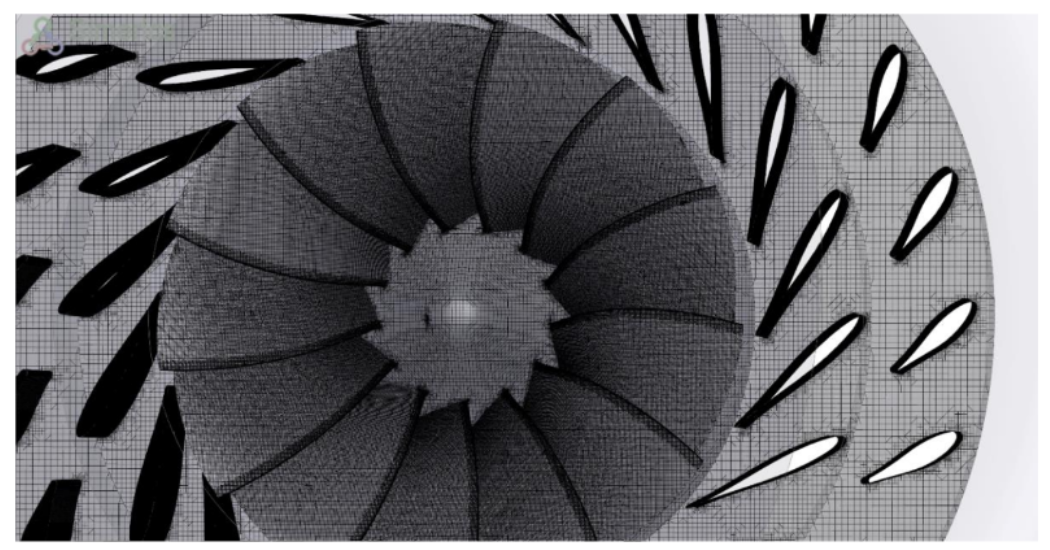
Figure 5 Computational Grid Simerics MP
6. Key Results
Data regarding the performance of baseline design and design 20 was extracted from SMP and StarCCM+ and plotted below. The following three charts showing efficiency, net head, and power over volume flow rate, are for one wicket gate angle at one rotational speed.
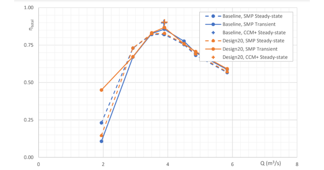
Figure 6 Total Stage Efficiency vs. Volumetric Flowrate
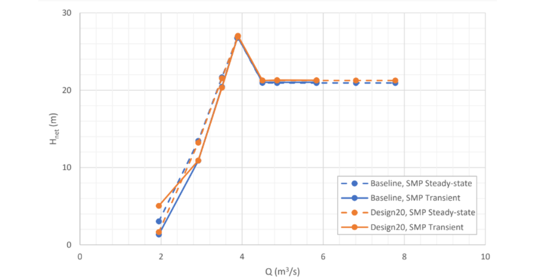
Figure 7 Net Head vs. Volumetric Flowrate
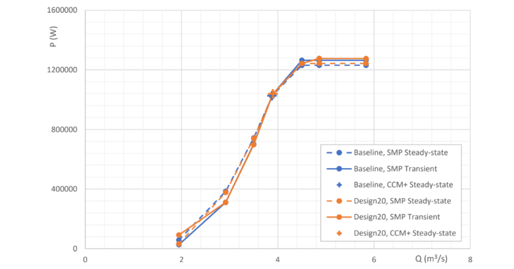
Figure 8 Shaft Power vs. Volumetric Flowrate
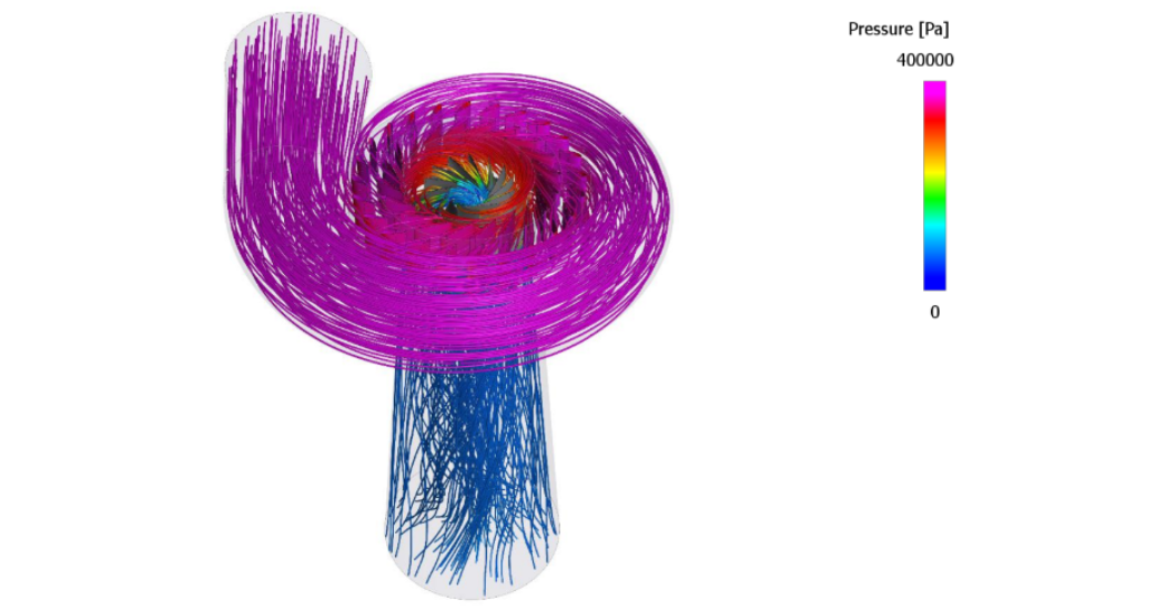
Figure 9 Static Pressure Streamlines CFturbo + SMP (Steady-state, 3.89 m3/s, 600rpm)
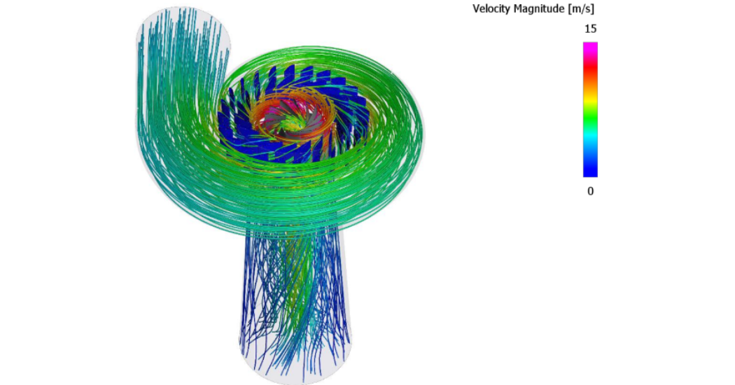
Figure 10 Velocity with Streamlines CFturbo + SMP (Steady-state, 3.89 m3/s, 600rpm)
The initial design point coincided with the best efficiency point. In terms of simulation precision, the transient results from Simerics MP more accurately agreed with the steady-state results from StarCCM+. This outcome is logical given the more refined quality of the
Star-CCM+ mesh and the Simerics-MP transient simulations using the corresponding steady-state results as an initial solution. As discussed previously, design 20 slightly outperforms the baseline design in terms of both total efficiency and runner efficiency at the best efficiency point.
The head loss is relatively high within the stay vanes, which could be a focus for future optimization. Figure 9 and Figure 10 show the pressure streamlines and velocity streamlines within the flow path of the device, respectively.
We see the typical offset between steady-state and transient results over the whole operating range when calculating net head and efficiency. However, the runner efficiency of about 90% is very remarkable because the Baseline design was an initial conceptual design just from CFturbo, without any optimization.
7. Conclusion
To this date, CFturbo is the first and only commercial software on the market that gives users the chance to create conceptually hydro turbine designs while exporting and integrating 3D geometry models in a subsequent process of simulation and optimization. As seen in this case study, CFturbo is compatible with a variety of engineering simulation software like Simerics MP and Star-CCM+. Design explorations can be made manually or performed using a CFturbo engineered Python script solutions. Furthermore, it is easily possible to combine CFturbo with third-party optimization software to apply various mathematical optimization algorithms conveniently. CFturbo integrates excellently with HEEDS (SIEMENS), DAKOTA (open source), optiSLang (Ansys), and others. With this, design and finetuned optimization of turbomachinery devices is not only possible but streamlined.
About CFturbo
CFturbo (est. 2008) is headquartered in Dresden, Germany, with a major office in New York City, NY. The company is supported by a global network of distributors and has gained worldwide respect within the Turbomachinery community over the last ten years. CFturbo is dedicated to Turbomachinery design and related engineering services in the design of rotating machinery, fluid flow, and heat transfer.
Our conceptual design software is the most user-friendly system available on the market through its unrivaled, intuitive, and user-friendly design process, CFturbo software empowers every user, regardless of experience. The software can be used to design a variety of turbomachinery-related devices, including pumps, fans, blowers, compressors, turbines, stators, and volutes. CFturbo, Inc. offers a variety of Turbomachinery engineering services including aerodynamic and hydraulic designs, CFD and FEA simulation, rotating machinery optimization, mechanical design, prototyping, and testing. For more information, visit cfturbo.com.
Works Cited
[1] P. Breeze and P. Breeze, “Hydropower,” in Power Generation Technologies, 3rd ed., Elsevier Science & Technology, 2019, pp. 173–201.
[2] R.Escher and R.Dubs, “Die Theorie der Wasserturbinen“ 3. Auflage, Springer Berlin 1924 (in German)
[3] R. Thomann, „Wasserturbinen 1./2.Teil“ 2. Auflage, Verlag K. Wittwer, Stuttgart, 1908 (in German)
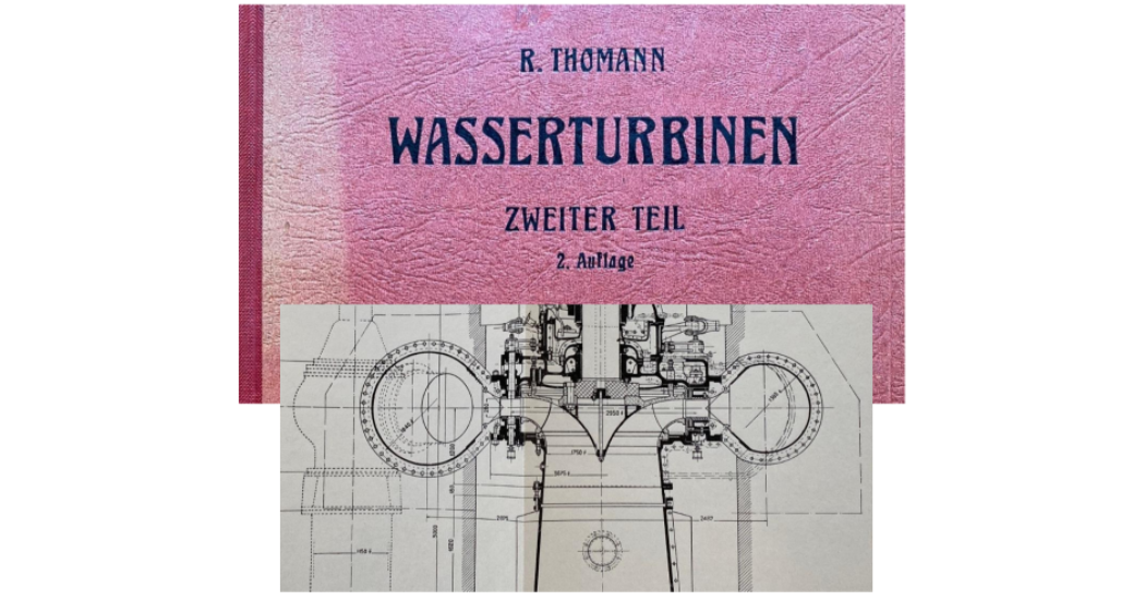 “By updating hydraulic design methods with CFturbo’s software, we will empower the next generations of engineers, using 100+ years of experience in sustainable power generation.”

Comments