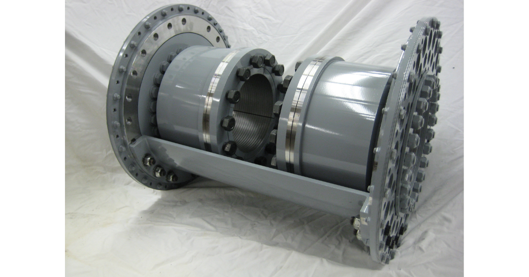
CCA offers several Close Coupled coupling designs to meet challenges that may appear with coupling applications. Typically the flexible members are placed further back on the shafts to increase the distance between the two flex planes. Normally the two ends are connected with a split sleeve so that the two machines can be connected without having to move anything. Engineering Data, Engineering Data Metric
In many applications, the distance between the driving and driven machines is very small. There could be many reasons, but generally it is due to lack of floor space. These types of applications may not accept a normal spacer coupling design. The spacer coupling may fit, but the distance between the flexible hinges would be very short, which reduces the offset misalignment capability of the coupling.
Split Sleeve Close Coupled Coupling
There are generally two different sleeve configurations used in a close coupled coupling. The first is where the sleeve is split axially into two pieces. The other option is to split the sleeve perpendicular to the rotating axis and adding a flange somewhere in the middle of the coupling. In this case the sleeve could be in two or three pieces. There are several factors which will help decide which configuration is best – speed, spacing, installation/removal geometry, bolt access, etc.
These pictures are an example of a close coupled coupling with an axially-split sleeve. The first shows half of the sleeve removed, and the other one shows the full sleeve in place.
In some cases it might be virtually impossible to move either piece of rotating machinery, which makes it impossible to install a new coupling. Coupling Corporation has a solution – a coupling that can be completely split in half. Even the Anderson Clamp Hub is divided into two halves.
Learn more about Coupling Corporation America.