Reciprocating Compressors
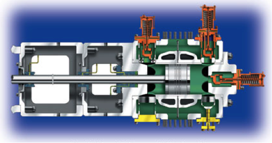
Reciprocating compressors (see Figure H) represent a class of gas compressors that raises the pressure of a gas by means of a tightly fitting reciprocating piston inside a cylindrical chamber, reducing volume from intake to discharge, in order to generate flow. Check valves within the cylinder are used to control the flow of gas within the cylinder.
http://www.machinerylubrication.com/Read/775/reciprocating-compressor
Reciprocating compressor components include:
- A piston with rings and rider bands, cross head, and piston rod, which moves back and forth with each rotation of the crankshaft. The rings act like seals to keep gas from bypassing the piston. Rider bands are wide ring shaped devices that support the piston in the cylinder and prevent the two from touching. Some reciprocating compressors are “single acting” and some are “double acting”. Single acting reciprocating compressors compress gas only when the piston is moving in one direction. When the piston moves toward the cylinder head the gas is being compressed but when the piston is moving away from the head, suction is pulling gas into the cylinder.
Double acting compressor cylinders compress gas on both movements of the piston. When the piston is moving toward the head of the cylinder it is compressing gas as well as putting it into the process. At the same time the piston is on the suction stroke of the crankcase half of the cylinder. When the piston begins to move toward the crankshaft the crankshaft half of the cylinder is on compression and the head end is on suction. The effect is that there is almost twice the output from a double acting cylinder as from a single acting one.
- A compressor cylinder contains the internal pressure and supports the reciprocating piston. The cylinder also has a head on each end with water passages to remove some of the heat of compression. The outer head may also include something called a clearance pocket for adjusting compressor output. The piston rod head has high pressure packing in it to keep the pumped gas inside the cylinder.
- A set of suction and discharge valves. Reciprocating compressor valves are essentially check valves. The suction valves permit flow into the cylinder but not back out, and discharge valves permit flow to exit the cylinder but not return back in. Suction and discharge valve failures are the most common component failure in a reciprocating compressor. Unloaders may be part of the suction valve assembly.
There are three ways of controlling the output of a reciprocating compressor that is motor driven (constant speed):
- reducing suction pressure;
- adding a clearance pocket to the cylinder by opening and closing the valve that separates the cylinder from the additional volume in the clearance pocket;
- activating unloaders on the intake valves, which will hold them open.
- A crank shaft, crank case, and connecting rods. Some reciprocating compressors have two lube systems, one for the crank shaft and cross head and another for the cylinder and packing. The lubricant may be the same in both lubricating systems, but in some cases is different. Be careful not to mix or switch the two oils if they are different.
If all the compression components are working properly, the flow through a compressor cylinder is controlled by 1) the compressor speed, 2) the displacement of the piston within the cylinder, and 3) the suction pressure. Increasing either the compressor speed, cylinder displacement, or suction pressure will increase the net flow through the cylinder and the horsepower required from the driver. However, the design flow through a compressor cylinder can be reduced by numerous factors, such as internal leakage at the piston rings or valves, preheating of the inlet flow because of high ambient temperatures, a fouled exchanger on the suction gas, a lower suction pressure, etc.
Reciprocating compressors are often equipped with valve unloaders and clearance pockets as a means of controlling compressor throughput. If these flow control components malfunction, compressor flow may decrease dramatically or even drop to zero. Unloaders are control elements designed to hold intake cylinder valves open when they are activated, so that no gas can be trapped or compressed inside the cylinder during the compression cycle. Therefore, any compressor cylinders with activated unloaders will not be able to contribute any flow to the compressor’s total flow. The more unloaders that are activated the lower the total flow will be. Unloaders may be operated independently or in groups to produce the desired number of compressor “load steps.” In contrast, clearance pockets are used to add or remove internal volume within a compressor cylinder, which in turn adjusts when the intake valves open and varies throughput. Generally, as flow is decreased with the use of unloaders and/or clearance pockets, the required horsepower decreases. Conversely, as flow is increased with the use of unloaders and/or clearance pockets, the required horsepower increases.
Troubleshooting Tips:
- If the differential pressure (i.e. the difference between the discharge pressure and the suction pressure) across any compression stage increases, the discharge temperature will increase on that stage. Conversely, if the differential pressure across any compression stage decreases, the discharge temperature will decrease on that stage.
- If the compressor speed increases, the net flow will increase. The horsepower required by a compressor increases at higher speeds, which should be reflected by increasing amps or kilowatts. Conversely, if the compressor speed decreases, the net flow will likely decrease. The horsepower required by a compressor at lower speed will decrease, which should be reflected by decreasing amps or kilowatts. This relationship between compressor speed and horsepower is not seen on motor driven compressors unless the motor is equipped with a variable speed electrical drive.
- If the molecular weight of the gas being compressed increases, the required horsepower will also increase. Conversely, if the molecular weight of the gas being compressed decreases, the required horsepower will decrease.
- If the suction pressure increases, the mass flow and required horsepower will also increase due to an increase in the gas density. Conversely, if the suction pressure decreases, the mass flow and required horsepower will decrease. If a higher suction pressure puts more gas into the compressor, more horsepower will be required to achieve the same pressure.
- If a multistage compressor begins to lift a relief valve between stages, the stage downstream of the relief device needs to be checked as it is not “keeping up” with the previous stage.
- If throughput falls quickly, check to insure all unloaders on intake valves are functioning correctly and not allowing the intake valves to close. If clearance pockets are used to control compressor throughput normally, insure the valve that controls their addition or removal from the cylinder volume are closed to separate them from the cylinder.
These relationships will help to troubleshoot reciprocating compressors that are not performing as expected. When reporting a problem with a compressor, always list the symptoms that caught your attention, such as a low flow, high amps, knocking sound, vibration, not enough pressure, etc.
Criticality
Compressors of all classes and designs should be monitored closely because they tend to be high-energy, high-horsepower machines. In many cases, they are unspared, which makes them highly critical to the processes they support. When they fail management takes notice.
Because compressors tend to represent the most critical machines at most sites, it makes sense to watch them closely and keep them maintained and operating efficiently.
This brief introduction about the compressors is really helpful. As I know reciprocating compressors are a type of gas compressor that creates flow by increasing a gas’s pressure by forcing a tightly fitting reciprocating piston to move back and forth inside a cylindrical chamber. It is the most critical machines at most sites, it makes sense to watch them closely and keep them maintained and operating efficiently. I would like to wait till I get some ideas from you and you never disappoint. There are lots of companies out there in the market like Zentech Systems & solutions. They had some good info indeed. I would like to check their blog also.