All types of pumps vibrate to some degree during operation. However, excessive vibration can have a negative impact on pump performance and life. Different factors can cause vibration such as hydraulic disturbances, mechanical imbalance of rotating parts as well as hydraulic resonances in piping. Excessive bearing housing vibrations (possibly resonances) can cause fatigue fracture of instrumentation or auxiliary pipes.
Determining allowable values for pump bearing housing vibration can help avoid mechanical problems and even pump failure. These vibration measurements can be used for acceptance tests, diagnostic or analytical investigations in addition to operational monitoring.
The following article provides guidelines on conducting bearing housing vibration measurement on rotodynamic pump applications absorbing more than 2kW (3hp).
Vibration Measurement Instrumentation
For pumps operating at speeds greater than 600 rpm, measurement of overall velocity in millimeters per second root mean square (RMS) or inches per second RMS should be used. A velocity or acceleration probe should be implemented to measure vibration at various frequencies, with measurements integrated into an electronic circuit to determine the overall RMS in the appropriate units.
Overall RMS vibration is a measure of the total RMS vibration magnitude obtained using instruments that integrate the vibration within a fixed frequency range over a fixed period of time. For pumps operating at less than 600 rpm, measurement of the overall peak to peak displacement is also required.
For all speeds, a 6-dB per octave filter, typically not present in processing software, should be used to filter out frequencies outside the measurement range to reduce electronic noise. For speeds above 600 rpm, the measurement instrumentation must be capable of measuring RMS velocity in the frequency range of 5 Hz to 1000 Hz. For pumps operating at speeds less than 600 rpm, the filter should measure RMS velocity and peak to peak displacement in the frequency range of 2 Hz to 1000 Hz.
Precautions should be taken to eliminate sources of error associated with transducer mountings, transducer cable lengths, transducer orientation, magnetic fields, temperature variations as well as electrical fields or poor grounding. Appropriate mounting methods for vibration transducers are shown in Figure 1.
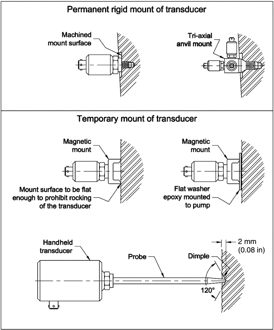
Figure 1: Permanently mounted transducers should be flat to within 0.025 mm (0.001 in) with a surface roughness of <3.2µm. Temporary mounted transducers also must have a flat surface with a diameter > mounting surface of the probe.
Measurement Locations for Different Pumps
The maximum vibration magnitude should be observed at the pump measurement locations as outlined in Figures 2 – 5. Measurements should be compared to the maximum allowable vibration values for a specific pump type, applicable test location (field or factory), and pump input power.
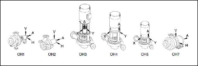
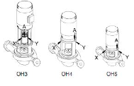
Figure 2: For end suction pumps, probe near the outer bearing, while for vertical mounted pump, probe near top of motor support.
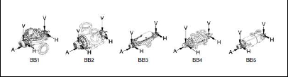
Figure 3: For between bearing pump types, probe location is at the bearing housing.
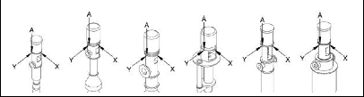
Figure 4: For vertical wet pit pumps, probe location is near top of motor support.
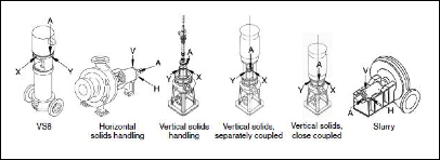
Figure 5: End suction pumps have a probe location near the outer bearing while vertically mounted pumps are probe near the top of the motor support.
General Conditions for Vibration Tests
If required by job specifications or contract, pump vibration acceptance tests are performed, with details outlined by involved parties. Vibration acceptance tests are typically conducted in the field. A factory test, however, is performed in the manufacturer’s test facility or at a test site. Pumps are tested at rated operating conditions. Higher vibration is to be expected in factory tests as compared to the field installation conditions.
Factory and field tests must be conducted under these general operating conditions:
- Balanced pump impellers (typically a single-plane spin balance)
- Operation under steady state at the rated speed ±10%
- Coupling alignment to pump manufacturer’s recommendations
- Bearing housing vibration level recorded as RMS maximum value in each plane
- No other equipment should be operating nearby during the test
The following additional conditions apply only to field tests:
- Measurements performed on pump bearing housings at normal steady state operating temperatures, except when vertically suspended pumps or factory tests are involved
- Pump operated at the specified or rated operating conditions (flow rate, head, and speed)
- Nozzle loads maintained
- Vibration with the pump not running < 25% of acceptable level
- No significant suction-related adverse hydraulic phenomena
Allowable Pump Bearing Housing Vibrations
The Hydraulic Institute Standard ANSI/HI 9.6.4 Rotodynamic Pumps for Vibrations Measurements and Allowable Valuespresents vibration level graphics that outline allowable pump bearing housing vibrations for different types of rotodynamic pumps including pump types BB, OH, VS as well as slurry and solids handling type pumps. Figure 6 is one such graph that indicates the allowable pump vibration for solids handling pump types. ANSI/HI 9.6.4 also outlines operating conditions and additional data for pump operation with the preferred and allowable operating areas.
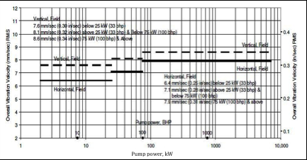
Figure 6: Solids-handling pump types. (Note: New pumps, operation in the preferred operating region (POR), tested with clear liquids. For operation outside the POR but within the allowable operating region (AOR), increase values shown by 30%.)
Many factors can affect pump vibration as outlined in Figure 7. Additional information on vibration sources and potential solutions, vibration transducer types, mounting and sensitivities is outlined in ANSI/HI 9.6.4 Rotodynamic Pumps for Vibrations Measurements and Allowable Values that can be purchased at http://estore.pumps.org . Also, watch for online webinars on this same topic that are conducted by the Hydraulic Institute periodically throughout the year. Currently scheduled webinars can be found at: http://estore.pumps.org/Webinars-C28.aspx.
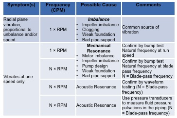
Figure 7: Vibration Source Identification Chart


Curious why we’d find it necessary to measure to 1000Hz in small pump applications. Frequencies of interest tend to be in the N x Running speed range, which is a pretty small number, particularly for lower speeds. For example, running speed for an 1800 rpm unit is only 30Hz. In my experience, the extended measurement range gives a plotted result with the most useful information condensed at the left end of the plot, which makes it more difficult to read. Additionally, sub-1x vibration can become very difficult to differentiate from 1x.
For multiple stages, high speed, and high energy pumps the large frequency range makes sense, but for small pumps it may be a detriment.
George, we believe you are commenting on the standard content, not the webinar presentation. It should be noted that the scope of the standard exceeds pumps that could be classified as small pumps. The frequency range up to 1000 hz matches at least two other pump industry vibration standards. Possibly this range is intended to capture cavitation effects, if present.
Your comment has been passed along to the Vibration Committee for consideration in future editions.