Variable speed pumping using a Variable Frequency Drive (VFD) can be a powerful tool in a pump system. However, incorrect application can do more harm than good, reducing the overall life of the pump and increasing operational costs. In this article, we will review some of the important considerations for a well-designed variable speed system in order to get the most out of your pump, but first let’s look at why you may or may not want to use a VFD.
Some of the most common reasons to use a VFD are soft starting or soft stopping a pump to prevent water hammer, compensating for unknown system conditions, or matching variable inflow to maintain the wet well level (providing a steadier flow to a WWTP and eliminating flow spikes). For all three of these cases, it’s important to ask “Is a VFD the most appropriate means for achieving what we want?” In order to make that decision, it is important to focus on some basics.
First, in order to make any accurate judgment of your requirements, you MUST know your system. This includes the overall piping length, the quantity and type of fittings used to calculate losses, the static head, and the inflow. These will allow you to accurately plot your system curve, which is crucial for making informed decisions about variable speed operation. If you do not know your system, it can be difficult to predict how your pump will react in a given situation and it may move into unfavorable operating conditions.
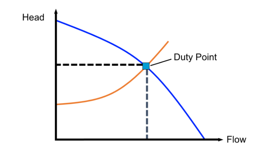
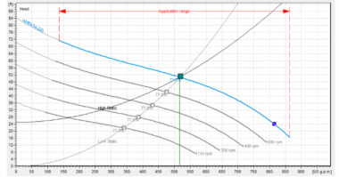
A pump operates where the system curve intersects with the pump performance curve. This is referred to as the duty point and it is the point where a pump will operate in constant speed operation. However, reducing the speed of a pump, will move the pump performance curve lower, thus changing the duty point. This has the tendency to move the duty point further and further left along the performance curve, potentially out of the Preferred Operating Region (POR) of the pump. The POR is defined by the Hydraulic Institute as the range along the pump curve from 70% to 120% of the flow at the Best Efficiency Point (BEP).
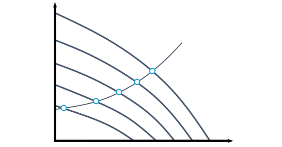
As performance moves to the left of the POR, internal recirculation may begin to occur in the pump hydraulic end, resulting in lower efficiencies and potential recirculation cavitation. These factors cause vibration-inducing high radial and axial forces, which can greatly reduce pump life expectancy.
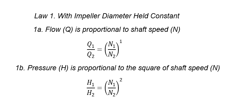
Something to consider, is that the higher the static head of the system, the flatter the system curve becomes, and the more the duty point will shift left. This is defined by the affinity laws, which state that while flow is proportional to shaft speed, pressure (head) is proportional to the square of shaft speed.
The example below shows both a system curve with low static head and with high static head that are both operating at the Best Efficiency Point (BEP) on a full speed performance curve. As the speed decreases, the low static head system remains operating at BEP, but the high static head moves progressively to the left of the curve.
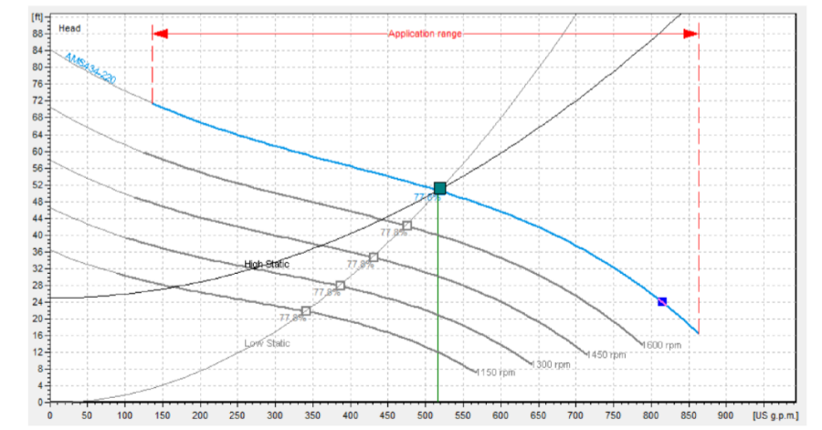
We can see in this example that variable speed pumping must be very carefully considered when designing systems with high static head, such as pump-down systems. In this application, it is often a better solution to use on/off regulation and/or parallel pumps in the system. Remember: an additional pump in a pump station adds redundancy that can reduce emergency callouts and lifecycle costs.
Even in a low static head system that is comfortably operating at BEP, another issue can arise. Low speed pumping is vulnerable to soft clogging and sedimentation in the piping. This is most commonly found in installations where a VFD is being applied to compensate for unknown system conditions, such as a retrofit.
Without knowing exactly what the system conditions are, it is very easy to simply decrease the pump speed until the desired flow is achieved and not worry about what is happening throughout the piping. However, as flow decreases with a VFD, so too does water velocity in the piping. If the velocity falls below the recommended minimum solids carrying velocity of 2ft/s (0.6 m/s) the system becomes susceptible to sedimentation in the line. It is important to always identify minimum operating speeds for your pump in order to prevent flow falling below the acceptable velocity.
In addition to hydraulic concerns, VFDs can also cause damage to pump motors without proper precautions. In order to achieve their intended purpose of simulating AC sine waves, VFDs utilize repeated, high voltage DC pulses. Without the usage of adequate power filters, such as a sine wave filter, these pulses can break down the winding insulation in motors that are not designed for the application, leading to motor failure. Even with windings designed to handle VFD applications, damage may result in the motor bearings from induced currents if they are not adequately insulated. This bearing damage is progressive and can eventually destroy the motor if not discovered. Always be sure to take adequate electrical protection measures when designing a VFD system as well.
Variable Speed Pumping, like any tool, is useful in some applications and detrimental in others, and it is up to engineers and designers to determine whether it is the correct tool for a given job. Work put in during the design and research phase can pay back many times over in preventing troublesome lifecycle issues that will haunt the pump and station for years to come.
Read about HOMA Pump’s A-Series Waste Water pump!


Comments