Authors: James M. Scott, Senior Project Coordinator – Large Machines, WEG Electric Corp.; Gerardo Elias Rodriguez, North and Central America Marketing Manager, WEG Electric Corp.
The Brightwater Influent Pump Station (IPS), located about 30 miles west of Puget Sound, has sent wastewater to the Brightwater Wastewater Treatment Plant since the IPS came online in 2011. The influent pump station collects raw sewage and pumps it two miles south to the wastewater treatment plant, which is built at an elevation approximately 235 feet higher than the IPS. With a 235-foot lift, which is considered a “high lift” for sewage pumps, the influent pump station installed four pairs of vertical non-clog sewage pumps to run in series arrangement. Though the pump station is designed to accommodate six pairs of pumps in its dry pit, the eight Fairbanks Morse pumps successfully transport approximately 17 million gallons of sewage to the wastewater treatment plant per day.
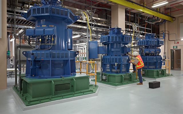
Each pair of pumps works in series at different elevations; that is to say, one pump, the first stage pump at elevation 57, pumps into the second pump at elevation 85. The sum total of those two pumps provides enough energy to push the raw sewage through the pipes to the wastewater treatment plant. Each pump sits on a pedestal and utilizes a 28 foot-long drive shaft to connect to the motor, which is not directly mounted on the pumps, but installed on the floor directly above. So for the pumps at elevation 57, the 700HP motors are installed on elevation 85; and for the pumps on elevation 85, the 1500HP motors are installed at elevation 109.
During start-up, pump station engineers found there was a surprising amount of surge in the system. Surge, which is sometimes called “water hammer” or “surge flow”, happens when there are rapid changes to the flowrate of fluid in a pipe. If a pump is running at a high flow rate, and there is an abrupt stop to the flow, either due to a power outage or some other reason, that interruption of flow can cause undesirable conditions, ranging from joint leaks and damaged supports to burst pipes and flow reversals. With more surge than had originally been planned for, the system required a modification to prevent surge from causing sudden reversal of flow through the pipes.
The pump station engineers began exploring options for controlling the unplanned surge in the system. They investigated surge tanks, which are large tanks that cushion surge by allowing liquid to enter or leave the pipe in the case of a surge event. Installing surge tanks at the IPS was not an attractive option for two reasons: large surge tanks, about 40 feet wide, would be unsightly and would create more maintenance responsibilities for the operations personnel who would have to clean the tanks.
Having crossed surge tanks off their list of possible solutions, the pump station engineers considered adding more inertia to the pumps so that flow would not be dramatically interrupted during a potential power outage. These pumps are all equipped with variable frequency drives, which, while VFDs typically ramp pumps down gradually to avoid surge, would not be able to do so during a power outage. Adding inertia to the pump motor system would enable the pump to continue to spin after the power has been interrupted. The more inertia that could be added, the longer the pump motor system could spin without power. If the pumps had enough inertia to spin down more gradually, then that would mitigate the system surge.
The pumps were driven by 700- and 1500-horsepower motors, which had been custom-manufactured by WEG Electric Corp. The initial motors had been designed with a considerable amount of inertia, with the 1500HP motors offering 15,000 lbs. ft.2 of inertia. However, hydraulic modeling and surge analysis determined that 51,500 lbs. ft.2 would be needed to offset the system surge. 51,500 lbs. ft.2 was a substantial amount of inertia, and it was questionable whether new motors could be manufactured to support the station’s new requirement.
Challenge Accepted
The engineers at WEG Electric Corp. accepted the challenge and figured out a way to build a 1500HP motor with 51,500 lbs. ft.2 of inertia and a 700HP motor with 11,467 lbs. ft.2 of inertia. After spending several months scrutinizing system specs and working their way through the engineering and design process, the engineers at WEG proposed a solution that incorporated the following features into the new motor designs:
Larger flywheels. While it is quite unusual to have a flywheel on a vertical motor, the initial WEG motors used a flywheel inside the motor to achieve the original inertia requirements. The flywheels are large, circular discs attached to the bottom of the rotor inside the motor frame. As the motor operates, the flywheel spins with every rotation of the motor shaft to create a reserve of available power in case there are any power cuts to the motor. With a substantial increase in required inertia, it made sense to increase the size of the flywheels. Cooling fans had to be built into the 4-inch deep flywheels to keep the motors cool.
| Flywheels for 700 HP Motors | Flywheels for 1500 HP Motors | |
| Material | Steel, ASTM A-36 | Steel, ASTM A-36 |
| Weight | 2,760.2 lbs. | 3,120.6 lbs. (+ fan 3,495.4 lbs.) |
| Inertia | 2,084.95 lbs. ft.2 | 15,396.05 lbs. ft.2 |
Larger, heavier rotors. To accommodate the larger flywheels and expanded load, the motors were designed with larger, heavier rotors. A complete motor rotor weighing 10,481 lbs. would be needed for the 700HP motor, and a complete rotor weighing 19,334.5 lbs. would be needed for the 1500HP motor. Of the 51,500 lbs. ft.2 of inertia required, about 36,000 lbs. ft.2 of inertia would be delivered from the larger rotor in the 1500HP motor.
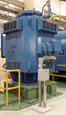
Larger motor frames. The new custom motor designs required larger motor frames for both the 700HP and 1500HP motors. WEG had manufactured the original motors, so they understood how the larger motor frames would have to be installed into the existing footprint (the pump station had been designed to accommodate the original motor frame sizes). While the larger motor frames for the 700HP motors would fit with no problem, installing the larger motor frames for the 1500HP motors would be more of a challenge. The 1500HP motors would need to sit in a frame more commonly used for a 5000HP motor. In order to use the wider motor frames for the 1500HP motors, each motor would have to be rotated about 45 degrees to optimize space. The rotation of each motor would provide adequate space to fit the larger motor frames into the pump station.
After many months of thorough evaluation, the IPS accepted WEG’s custom motor designs and went ahead with the order for (qty. 4) 700HP motors and (qty. 4) 1500HP motors. The next challenge was to get the new motors into the pump station. The motors were not only bigger, they were also much heavier. Each 700HP motor was 30,864 lbs., and each 1500HP motor was 48,500 lbs.
The weight of the larger motors exceeded the lifting capacity of the pump station’s gantry cranes, so the IPS replaced one of their cranes with a larger one. The larger crane increased their lifting capacity to 22-tons, or 44,000 lbs., which still wasn’t enough to get the 1500HP motors into the station. The IPS received permission to exceed the load limit of the crane by completing a Planned Engineered Lift (PEL), which allowed them to safely lift a load 1.25 times the rated capacity of the crane. The PEL increased their lifting capability to 55,000 lbs. and enabled them to install the new 1500HP motors.
The new WEG motors were installed the summer of 2014, and the pump station engineers performed a surge test on the whole system in October 2014. They stored up a significant amount of flow, started the pumps at max performance, and cut power to the motors. “The surge testing showed positive results, proving the performance of the WEG motors and their ability to alleviate potential surge issues that might arise at the pump station,” explains Richard M. Andrews, PE / PMP / Engineer V at King County Wastewater Treatment Division. “The WEG motors have been operating reliably and to the satisfaction of the pump station operators for over two years.”
For many pumping stations, it is common to have “unforeseen” issues at start-up. This is the reality of owning and operating a pump station. In this particular case, everybody involved stepped up to the plate to solve the surge issue, resulting in a win-win resolution.
Learn more about water solutions from WEG USA.


Comments