A Look Into The Carbon Graphite Production Process
Carbon graphite has a unique set of physical properties that allows it to be used in environments where self-lubricating materials and traditional lubricants will fail.
It can withstand high temperatures, corrosive media, and dry atmospheres, all while maintaining a low coefficient of friction, remaining dimensionally and thermally stable, and avoiding galling and seizing.
Over the course of many decades, thousands of carbon grades have been developed to handle a wide range of applications. As a result, carbon graphite can be found in countless severe service applications, ranging from jet engines to bakery ovens.
Carbon graphite’s versatility is directly attributable to the highly engineered processes that go into its production. A quick look at the processes involved in carbon graphite production highlights the complexity of this material and the importance of maintaining strict controls throughout the production process.
The Building Blocks Of Carbon Graphite Materials
Generally speaking, mechanical carbon-graphite components are made from two things: Powders and Binders. Raw powders are the component of carbon graphite that provides self-lubricating properties. These powders may include natural or synthetic graphite, carbon black, calcined petroleum coke, or other forms of carbon that are often mined from the earth or derived from byproducts of the refining industry.
Binders, on the other hand, are the “glue” that holds the powders together. These binders, which are often coal tar or petroleum pitch, soften when exposed to heat, and uniformly coat the carbon powders as they are mixed together. The resulting mix is then milled down to specified particle sizes, depending on the ultimate material grade. At this point, the powder can be moved on to the next step of material production: molding or extrusion.
Pressing It All Together: Methods To Creating A Solid Carbon Graphite Component
Once the ingredients are mixed and milled to a specific particle size, they are then “pressed” together to become a solid component.
There are three main methods by which this is done, each of which results in different final material properties:
- Isomolding | Isomolded carbon graphite is iso-statically pressed, meaning a constant pressure is applied to all sides. This results in an anisotropic, fine-grained material. This method is normally used for some of the finest grain carbon grades, often used as electrode material for EDM (electrical discharge machining) or steel manufacturing applications.
- Extrusion | In this method, the mixed powder is pushed through a die of a certain cross-section, resulting in a relatively softer part with a coarse grain size. As a result, extruded carbon grades are typically used in lower duty applications (i.e. board dryer bearings and water pump bearings).
- Compaction Molding | This method is most common for mechanical carbon-graphite components, as it allows for the most control over part uniformity since parts can be molded to more “near net” dimensions. In this method, the mixed powder is pressed between two punches to form a green part. Parts are typically molded as cylinders with an ID, since the final mechanical carbon-graphite components (e.g. bearings and seals) are usually cylindrical or are easily machined from cylindrical blanks.
It is important to control the density of green parts, since density has a major impact on many material properties throughout the remainder of the production process and ultimately, the properties of the final product. An improper green density can result in insufficient impregnation pick-up, decreased strength, and poor wear properties. This is why carbon graphite manufacturers monitor and inspect green density diligently.
When a batch of green parts has been molded and inspected, it can then move on to the next step of the process: baking.
Time To Bring The Heat: The Carbon Graphite Baking Process
At this point in the process, the green material begins to resemble something that looks like a finished component, but it does not yet have the strength of a finished part. The binder has not been hardened yet and is just acting as a relatively weak adhesive holding the powders together.
The green material must be sent through a controlled, oxygen-free baking process to carbonize the pitch binder and turn it into a very strong amorphous carbon. This process takes place in batch or continuous ovens, where the atmosphere and temperatures are closely monitored to ensure proper baking parameters.
Since the material needs to spend a certain amount of time in each temperature zone, it takes up to several weeks for a part to enter the oven and come out as plain carbon graphite.
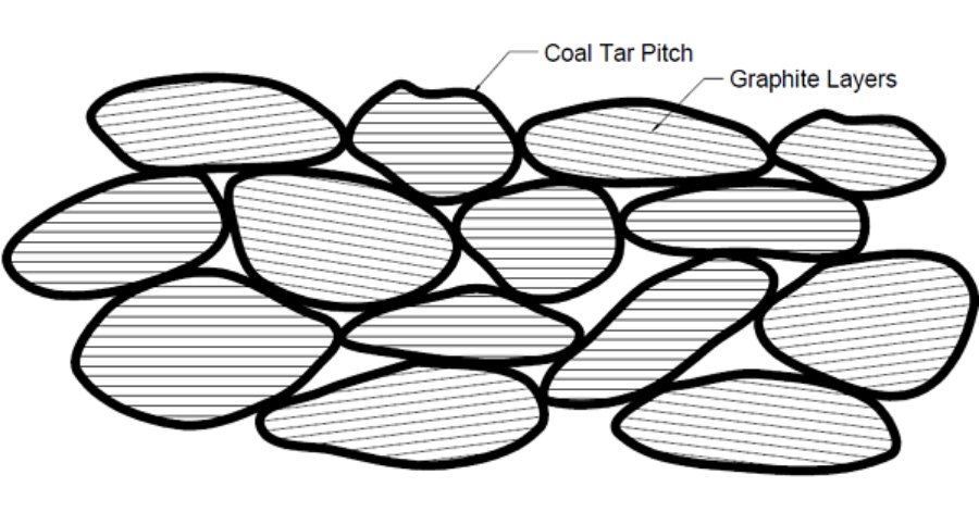
The diagram above shows a microscopic view of “green” carbon graphite.
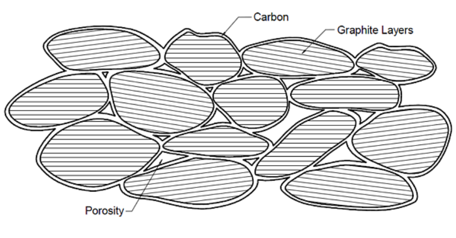
The diagram above shows carbon graphite that has been sent through the baking process.
During the baking process, outgassing of the binder occurs, meaning hydrocarbons in the pitch are driven off due to the extreme heat, leaving behind an amorphous carbon structure. During outgassing, these gasses push their way out of the material, leaving behind a network of interconnected porosity.
Due to outgassing, plain carbon graphite is an inherently porous material. Carbon graphite manufacturers are able to take advantage of this network of porosity by impregnating it with various substances.
The type of impregnation used is highly application-dependent, which is a topic we will address in Part II of this blog series.
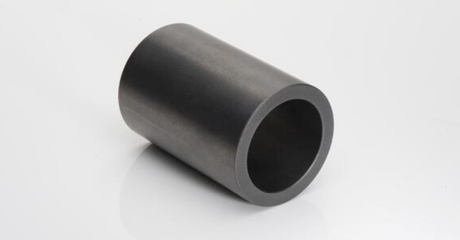
Plain carbon graphite bearings are widely used in many types of industrial applications.
Recap
From mixing and milling to molding and baking, all mechanical carbon-graphite components must undergo the same manufacturing steps (or at least very similar versions of these steps) up to this point.
The manufacture of plain carbon graphite is time- and process-intensive. But material processing often does not end there. In addition to the many different types of plain carbon graphite, there are also many different post-bake processes that plain carbon graphite can undergo to further enhance certain material properties for specific applications.
It is for this reason that there are thousands of carbon grades in existence today. Many of these processes will be discussed in further detail in From Powders to Parts: A Look into the Carbon Graphite Production Process (Part II).

![Durlon Chemap® filters solve filtration tasks in a simpleand economic way [Case Study]](https://test.empoweringpumps.com/wp-content/uploads/2022/12/Durlon-Chemap®-filters-solve-filtration-tasks-in-a-simpleand-economic-way-Case-Study-7-380x199.png)
Comments