At one point last summer, I found myself laying in my bunk on board the 40 foot sailboat the Lillian B., counting the number of pumps she had on board. We were in the High Arctic, attempting to sail the fabled Northwest Passage and this mental exercise was motivated as much as a distraction from cold toes as it was from my curiosity as a pump engineer. Given the surprising number of pumps, the diversion was working. Counting from stem to stern, the number grows to over 15 pumps. If other turbomachinery are included, such as fans, compressors, and turbines, the count grew to over 25. Some of the pumps are mission critical to the boat’s operation, some are for safety, while others offer conveniences commonly found on land. In addition, the type of pumps varies as well: From diaphragm to centrifugal to positive displacement. The image below shows a sampling. It does not include all devices, such as the air pump for the inflatable dingy, the hand held emergency water maker, or various fans for cooling people and electronics.
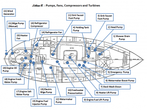
- Jabasco Jabsco Par-Max Shower Drain/General Purpose Diaphragm Pump – 3.5GPM-25psi
- Raritan PHII
- Whale Gusher MK3 Foot Pump
- Whale Gusher Titan Diaphragm Pump
- Rule 3700 gph Centrifugal Pump
- Watermaker centrifugal boost pump
- 12vdc ShurFlo #2088-423-344 saltwater centrifugal wash-down pump
- Heater lift pump
- Engine lift pump
- Freshwater pressurization Shurflo Centrifugal #2088-423-344
- Whale Gusher MK3 Diaphragm Foot Pump
- 12vdc Village Marine Tec Watermaker (Positive Displacement: Reciprocating Plunger)
- Bilge Diaphragm Pump
- 12 volt fan
- High Pressure Engine Fuel Injector Pump
- Engine Driven Seafrost Compressor
- Salt water cooling pump (Centrifugal with a flexible impeller).
- Freshwater cooling pump (Centrifugal with a rigid impeller)
- Engine oil pump (Positive Displacement)
- 12 volt Heater Fan
- Henderson diaphragm hand operated bilge pump
- Fourwinds Wind Generator
A review of the pumps and equipment on board starts in the head (bathroom) which is immediately aft of the forward cabin. It alone features four pumps. The first is an electrically driven diaphragm pump (#1) hidden below the flooring and used to drain water after the infrequent fresh water shower. The water for the shower comes from two 70 gallon fresh water tanks, contained in the settees on either side of the main cabin. The system is fed via an accumulator, pressurized by a centrifugal pump (#10) located amid ship.
Next to the shower is a marine toilet, with an all-important hand-operated diaphragm pump (#2) used to pump waste into a holding tank or directly overboard when far enough out at sea as to not pollute nearby shores. Given the unpleasant prospect of a toilet that fails to operate, we carried a complete set of spare parts for this pump. And a second hand-operated diaphragm pump (#4) is connected to the holding tank, enabling it to be pumped overboard when more than three miles from the nearest ocean coast.
The head also includes a sink that can be filled from the freshwater tanks via a small spout using a foot-operated diaphragm pump (#3), or via a standard faucet fed by the fresh water system when pressurized. Two advantages of the foot operated pump are that it 1) does not require the system to be pressurized and 2) delivers measured quantities of water, helping conserve a precious resource. In contrast, the standard faucet is harder to regulate and can be inadvertently bumped open or left on. Out of the concern of unintentionally pumping the entire fresh water supply overboard, we took the unusual precaution of securely duct-taping this faucet shut for the entire voyage.
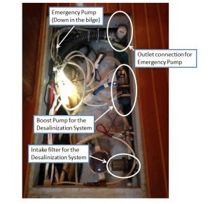
In the main cabin, slightly aft of the head, is one of the most important pumps on the boat, yet one that would hopefully never be called into action. Located in the bilge, beneath removable floor boards, is a high capacity centrifugal pump (#5) added as a safety precaution in preparation for arctic sailing where there is the real possibility of hitting ice and breaching the hull. Ice has a compressive strength similar to steel and the hull of the Lillian B is fiberglass, so a collision even at the speed of sail has the potential for catastrophic damage.
Dave Johanson onboard the Lillian B, ready to fend off ice
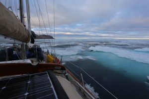
Lillian B. in the ice, Blanley Bay NU (Photo by Dave Johanson, Crew Member)
The emergency pump operates on 12 volts and draws 14 amps of current thus consuming 168 watts and enabling a healthy pumping rate of 3700 gallons per hour (3.89e-3 m3/s). The pump intake is located low in the bilge where any incoming seawater would first collect. Stored in a nearby locker was over 20 feet of flexible hose, ready to be attached to the pump outlet and directed up through the hatch and then overboard. This system would buy time in the event of a collision, but even at the respectable flow rate of 3700 gph, the pump would only be able to keep pace with flooding from a small hole, such as a 12.5 cm2 (1.9 square inches) crack in the hull, 0.5 meters (1.64 feet) below the water-line. This estimate is based on Bernoulli’s equation, where the kinetic energy of water pouring through the hole would be equal to the drop in gravitational potential energy from the surface to the damage, as follows:
12ρV2=ρg∙∆h
where ρ is the density, g is gravity (9.8 m/s2), and Δh is the change in height in meters. Solving for V with a value of 0.5 meters for the depth of the impact gives a velocity of 3.1 m/s pouring through the hole,
V=2g∙∆h
The corresponding flooding rate would be the velocity times the area, such that the emergency pump would be only able to keep up with the seawater from a hole of area equal to or less than 12.5cm2 (1.9 square inches)
Area=Pumping Capacity/V
Any bigger crack and we would be frantically trying to stem the flow.
Desalinization Boost Pump
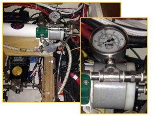
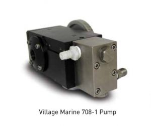
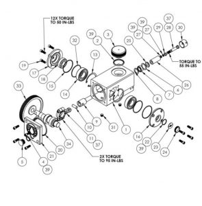
Next to the emergency pump, seemingly insignificant in comparison, is a small centrifugal pump (# 6) serving to prime the desalinization system. Although the Lillian B has tanks for storing over 140 gallons of fresh water, our primary source of drinking water came from a 12 volt Village Marine Tec Watermaker which produces fresh water by using a positive displacement pump (#12) to force seawater against a membrane at pressures over 800 psi (54 atmospheres), creating a reverse osmosis process operating around 100 watts to generate fresh water at approximately 8 gallons per hour.
Tec Watermaker High Pressure Parker Hannifin Desalinization Pump
The remaining pumps inside the main cabin include:
- A salt-water pump (#7), connected to an outside fitting, for washing the deck,
- A lift pump (#8) to provide diesel fuel to the cabin heater,
- A lift pump (#9) for engine fuel,
- A second foot-pump (#11) for the sink, and
- A standard bilge pump (#13) activated by a float switch to automatically pump out any water that finds its way into the boat through spray or condensation.
Outside the cabin, in the cockpit, is a hand-operated diaphragm pump (#21) which provides a third means of pumping out the bilge, although at a much slower rate than the emergency pump (#5).
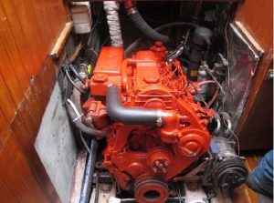
Opening the engine compartment beneath the cockpit reveals the various pumps needed to keep the 55hp Westerbeke diesel engine operating smoothly:
- A high-pressure, fuel pump (#15) to feed the injectors.
- A salt water centrifugal pump (#17) for cooling
- A fresh water centrifugal pump (#18) for cooling and
- An oil pump (#19) for lubrication
The Westerbeke diesel engine revealed (with some components temporarily removed for service.)
The Lillian B also includes non-pump turbo machinery, such as:
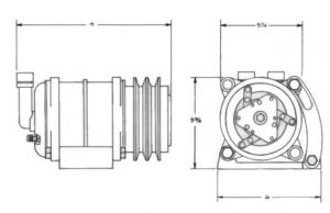
- An engine driven compressor for the refrigerator in the galley (#16), and
- Various fans for circulating heat and air (e.g. #20)
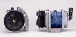
The 6 cylinder swash plate Seafrost compressor for refrigeration
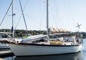
And, finally, mounted on a pole at the stern of the boat is a Four Winds Wind Generator
(22) that serves as an alternative energy source to supplement the engine driven alternator. In a stiff breeze, the Four Winds recharges the battery bank at a rate of approximately 75 watts.
Lillian B with a Four Winds Wind generator on the stern
The design challenge for a wind generator is to create a device that is efficient at low wind speeds, yet can survive the force of high winds. The Four Wind generator we had on board was an older model and not as efficient as some others we encountered, but unlike some more efficient designs, it survived the near hurricane winds that could appear in the Arctic without warning.
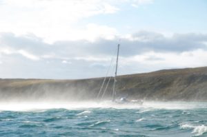
The yacht Suilven at anchor, riding out 60+ mph winds in Dundas Harbor, (74o 30’ N, 82o 42’ W) August 8th, 2014 (Photo Courtesy of John and Linda Andrews)
In theory, a sailing vessel could cross an ocean without the assistance of turbo-machinery, but even the ships of Christopher Columbus had bilge pumps. Adding pumps and fans for household systems adds comforts not found in vessels that first crossed the seas over 500 years ago. Without water, fuel and oil pumps, the convenience and safety of a diesel engine would be impossible. And the presence of a wind generator for power combined with a high pressure pump to generate fresh water from the sea provides a remarkable self-sufficiency, in stark contrast to arid lands dependent on the whims of nature for fresh water. But even counting these modern systems, my toes still knew it was cold (< 10oC) inside the boat.
About the Author:
Dr. Sam Lowry is owner of the Lillian B. and President of Simerics Inc (www.Simerics.com ) , developers of the computational tool PumpLinx simulating turbomachinery . For more details on the attempted transient of the Northwest Passage, see www.LillianB.net (Logbook/2014 NWP).
The author would like to thank Johanson Boatworks for their work in preparing the Lillian B for the Arctic and for their help in preparing this article.




Comments