No, it is not the place where good alignments get lost – never to be seen again! It is a way of thinking about locating machinery feet so that the shafts are in alignment, even when the feet of the moveable machine may be a few thousandths up, down, left, or right of perfect. Shaft alignment is about aligning the shafts, not the feet.
Think of the shafts as two straight lines – one stationary, representing the stationary machine, and one moveable, representing the moveable machine.
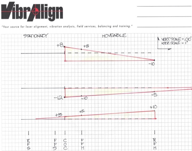
In the top graph, the rear foot moveable is 10 mils low, and the front foot moveable is 5 mils high, but the result at the coupling is 8 mils high.
In the middle graph, the rear foot moveable is 5 mils low, and the front foot moveable is 10 mils low, but the result at the coupling is 12 mils low.
In the bottom graph, the rear foot moveable is 10 mils high, and the front foot moveable is 5 mils high. The result at the coupling is 3 mils high.
Simply put, the “triangle” formed by connecting the foot positions to the reference line should point toward the coupling, not away from it. Remember this simple rule of thumb:
- The value of the rear foot moveable (outboard) should be bigger.
- The value of the front foot moveable ( inboard) should be smaller.
- They should both be the same sign. In other words, if one is a +, both should be a +.
- If one is a -, both should be a minus.
For a better explanation, please read the article Don’t Look at Your Feet by VibrAlign’s founder and CEO, David Zdrojewski. Click on the link below.


Comments