There are many types of tools with which we can perform an accurate shaft alignment. For most of us, laser alignment is considered the most accurate and effective. But shaft alignment can be done with reverse dial indicator sets, or dial indicators and chain-type brackets, or a straightedge, feeler gauge, and an outside caliper.
Regardless of what you use, here are some easy things that can be done in 15 minutes or less, and can make shaft alignment faster, and more effective, regardless of the method employed.
VISUAL INSPECTION
Spend a couple of minutes looking over the machine, and ask yourself these questions:
- Is this machine safe to align? Have all Lock Out/Tag Out/Valve Out procedures been completed?
- Are hold down bolts tight on both the stationary and the moveable components?
- Are the couplings mounted correctly?
- Are the set screws tight?
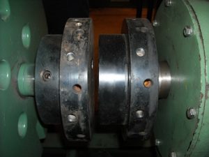
- Is the axial spacing between the coupling flanges correct?
- Can the shafts be rotated?
- During rotation, do you hear unusual noises, such as a bad bearing or rub?
- Is there excessive backlash noticed in the coupling? Is it due to wear? Should the coupling insert be replaced before alignment is performed?
- Are the coupling flanges concentric? Verify with a dial indicator to be sure.
- Does pipe strain exist in the system, especially near the components to be aligned? Perform a quick visual inspection of the piping system to determine if pipe hangers or other supports are installed correctly.
- Is the machine base structurally sound? Do you notice large cracks in the grout or broken welds in the base?
- Is the machine base mounted solidly to the floor or support structure?
- Have jacking bolts been installed on the machine? Make sure they are not touching the component feet before performing aligning.
- Do you have the proper tools, measuring instruments, and shim to complete the alignment?
SOFT FOOT MINIMIZATION
If soft foot is not minimized, it will complicate the alignment, and slow the process down considerably.
Loosen all foot bolts on the moveable machine. Using a pry bay, apply slight lifting force under the foot, and measure for soft foot with a shim, or feeler gauge. Add shim as needed to correct for soft foot. Then continue on to the other feet on the moveable machine, until a 0.002-0.003” shim or feeler gauge cannot be inserted under the foot.
ROUGH ALIGNMENT
Using a straightedge, check the tops of the coupling flanges for parallelism. If a gap exists while checking for parallelism, measure the gap with a shim or feeler gauge. Insert the measured amount of shim under each of the moveable machine to bring the components into rough vertical alignment. Repeat the procedure on the sides of the coupling flanges to correct for rough horizontal alignment. Be sure to tighten the feet of the moveable machine back down before beginning alignment.
After completing the rough alignment process, you are now ready to begin alignment.
Last year, while teaching a training class, I was asked to take a look at a machine the class wanted to align. After a quick look at the machine, I found a serious problem that needed addressing before we began the alignment.
For more information, please visit VibrAlign.com


i want to know more about alignment of Pump & Equipment