Author: Robert X. Perez, Machinery Engineer
Centrifugal Compressors
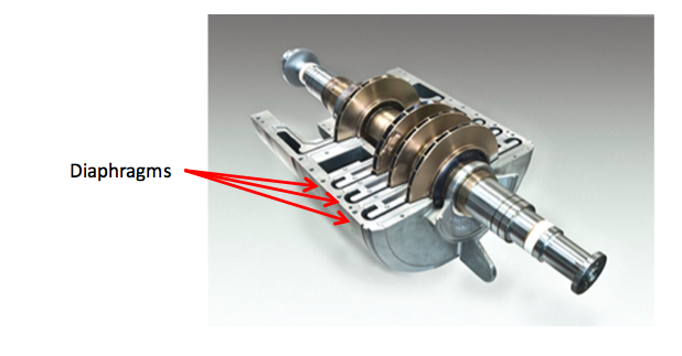
Centrifugal compressors are a class of gas compressors that operates similarly to centrifugal pumps. The gas enters the eye of an impeller and is accelerated outwardly toward a stationary diffuser that decelerates the gas stream and creates pressure. Typically, multiple stages of impeller/diffuser sets are required to generate the required differential pressure (see Figure F). The key components that make up centrifugal compressors are the rotor, rotor support bearings, end seals, diffusers between impeller stages, and a pressure casing. The rotor spins inside a pressure containing casing that houses the diffusers, which are designed to convert high velocity flow off of each impeller into higher and higher pressures, until flow reaches the discharge nozzle. Centrifugal compressor performance curves are similar to those of centrifugal pumps. They show that the pressure rise, i.e. discharge pressure minus the suction pressure, across a compressor increases as speed increases and drops as the flow through the compressor increases (see Figure G).

Figure F—A partially disassembled multistage centrifugal compressor showing the rotor, casing, and flow diaphragms. Diaphragms guide the gas flow from one compression stage to the next.

Figure G—Centrifugal Compressor Performance Curve
Troubleshooting Tips:
Here are some useful relationships to remember when dealing with centrifugal compressors:
- If the pressure on the discharge pressure gauge increases, the flow is likely decreasing. Conversely, if the pressure on the discharge pressure gauge decreases, the flow is likely increasing if the suction pressure remains the same..
- If the compressor speed increases, the flow and discharge pressure will likely increase. The horsepower required by a compressor increases at higher speeds, which should be reflected by increasing amps or kilowatts if the compressor is motor driven. Conversely, if the compressor speed decreases, the flow and discharge pressure will likely decrease as with a turbine driven compressor. The horsepower required by the compressor at lower speed will decrease, which should be reflected by decreasing amps or kilowatts on motor driven compressors or decreasing steam input to the turbine.
- During start up and shutdown or upset conditions, the gas composition can change. If the molecular weight of the gas being compressed increases, the discharge pressure will increase and the required horsepower will also increase. Conversely, if the molecular weight of the gas being compressed decreases, the discharge pressure will decrease and the required horsepower will decrease.
- If the suction pressure increases, the discharge pressure will increase and the required horsepower will also increase. Conversely, if the suction pressure decreases, the discharge pressure will decrease and the required horsepower will decrease. All else being equal, a compressor is a differential pressure machine. Whatever goes in at one pressure will come out at a designed multiple pressure increase. If you raise the inlet pressure, the discharge pressure will also increase by the multiplier of the increase in the inlet pressure.
- Monitor the compressor balance line for temperature differences over time. A significant change can mean a balance piston seal problems, which can result in damaged thrust bearings.
These relationships will help to troubleshoot a problematic centrifugal compressor. When reporting a problem with a compressor, always list the symptoms that caught your attention, such as a low flow, high amps, leaking seals, vibration, not enough pressure, etc.
Tip of the Month: Rules of Thumb for Bearings
Tilting pad, sleeve, and thrust bearings are vital to the operation of centrifugal compressors. Radial bearings support the rotor and the thrust bearing maintains the axial position of the rotor within the casing. To function properly, the bearing-to-rotor clearances must be maintained within healthy ranges. Below are rules of thumb for centrifugal compressor bearing-to-shaft clearances and thrust bearing float ranges.
Rules of Thumb for Bearings
By Neal Wikert
(These rules of thumb were originally published on Rotating Machinery Services’ website at ww.rotatingmachiner.com. Reprinted with permission)
Bearings – Tilt Pad
A minimum bearing clearance should be the shaft diameter plus 0.001”. Another way of determining bearing clearance would be 0.00125” per inch of shaft diameter.
Bearings are considered worn when they are above 140% of the maximum clearance.
To determine the actual clearance of a tilt pad bearing use the following formula:
Actual clearance = Bump check times 0.89 (Lift value x 0.89)
Bearings – Sleeve
The normal bearing clearance is 0.001″ per inch of shaft diameter + 0.001″, i.e. 5″ shaft = 0.006″ (Inside diameter =5.006″). Alternately, the clearance should be .00125″/inch of shaft diameter.
The bore of normal babbitt bearings typically carry a 32 rms finish and are turned. No grinding is done on babbitt because it will clog the grinding wheel. Babbitt begins to melt at 450 oF and creeps at 275 oF.
Bearings – Thrust
Copper backed shoes and offset pivots can add 20% to typical load capability because of better heat transfer.
Thrust Float – Use 0.0015” (x) the bearing O.D. For example a 12” O.D. thrust bearing should have 0.018” axial float.
Lubrication
The most common oil used in turbomachinery is an ISO 32 (150 SSU at 100 degrees F.) However, always check with the original equipment manufacturer if you are not sure what lubricant you should be using.
Oil is usually supplied at 110-120 degrees F. and 15-25 psig. Bearings are designed/orificed for specific oil supply temperatures and pressures. Off design supply conditions can starve the bearing and cause overheating.
Temperature Monitoring
Temperature detector placement should be located 1/16th inch below the babbitt bond line – Avoid placing into the babbitt. It is recommended that the alarm be set at 235 oF. and the shutdown set at 250 oF.
About the Author:
 Robert X. Perez has over 30 years of rotating equipment experience in the petrochemical industry. He earned a BSME degree from Texas A&M University (College Station), a MSME degree from the University of Texas at Austin, and is a licensed professional engineer in the state of Texas. Mr. Perez served as an adjunct professor at Texas A&M University-Corpus Christi, where he developed and taught the Engineering Technology Rotating Equipment course.
He authored four books and coauthored four books in the field of machinery reliability. Mr. Perez has also written numerous machinery reliability articles for numerous technical conferences and magazines.

Comments