In this video, we’ll be demonstrating the aerodynamic design of an axial compressor rotor.
In particular, this presentation is about the main design steps for a transonic axial compressor rotor within CFturbo. We have defined an example compressor case called the “CFturbo Rotor21,” with similar operating conditions to the “NASA Rotor37”.
First you create a new project choosing the compressor design module. Insert the design point of the fan. The design point is defined by mass flow rate, total pressure ratio, and rotational speed. In this case, the fluid is air at 20 degrees Celsius. You can choose any fluid properties by choice, or by applying fluids database. The rotational direction or inflow swirl can be specified, if required. On the right side you’ll see the general machine type based on a specific speed calculation. In the Cordier-diagram fundamental relations of Specific Speed, Specific Diameter, Flow Coefficient and Work Coefficient are shown.
Now we add a new component, selecting the “New axial impeller” option. The main dimensions window opens. In this example we use an unshrouded, standard impeller, setting the tip clearance to 0.4 mm. We have two general options for blade design: “Airfoil” or “Meanline” mode. Here we have chosen the “Airfoil” method. In CFturbo there is also an option for multistage design, including contra-rotating impellers.
To calculate the impeller main dimensions, CFturbo uses numerous empirical correlations in the parameters section. In most cases, non-dimensional approximation functions are taken from textbooks, research papers and our own data. Here we use the work coefficient to calculate the impeller diameter, and a diameter ratio function to get the hub diameter. Additionally, several empirical efficiency correlations are implemented too to get reasonable initial values of the impeller main dimensions.
The impeller main dimensions are computed. In CFturbo all geometrical parameters can be adjusted manually if required. Here we modify hub diameter and impeller diameter slightly. This will only have a minor influence on subsequent design steps.
The meridional view allows the design of the meridional contours of the impeller.
On the right side of the window there are diagrams for area progression, static moment and curvature which can assist you in shaping the meridional contour of the impeller. A 3D preview is available too.
All Bezier points can be modified numerically by changing numbers in the pop-up window.
The user can adjust axial length of the impeller, as well as shape and position of leading and trailing edge in “Meanline Design Mode”. For “Airfoil Design Mode” which is used here one has to set only the limits of the axial positions. Chord length, stagger angle and camber angle of the blades will be calculated.
Now we add hub solids. For example, we can split the curves or transform them into Bezier splines. For demonstration purposes, we’re choosing a very simple model of the hub contour. This tool is very flexible for modeling hub, and shroud geometry if applicable.
In the blade properties, at first, we set the number of blades, which is an input value with strong effects on the blade profile geometry. The number and the distribution of spans in radial direction must be defined.
Next a method must be selected to calculate the radial equilibrium from hub to shroud, the cu-cm distribution. The circumferential and meridional velocity components can be adjusted to balance pressure and centrifugal forces. In many cases it is useful to choose the “variable load” option that enables you to shift the blade loading from hub to shroud. Here we don’t modify the “free vortex” option.
In the “Profile” window the user selects blade profile. It could be done from a NACA profile catalog, or by point-based data. User-defined blade profiles can be easily implemented. For this demo we have selected an NACA 65-006 profile. In this case we have adjusted the solitdy l/t, the relation between chord length and pitch. Profile properties stagger angle, chord length and camber angle can be calculated in automatic mode, or adjusted manually.
In the right side there are several diagrams with aerodynamic values and criteria to evaluate the profiles, for example solidity, Reynolds number or De-Haller criteria, among others.
In the next window there is the actual status of the blade profiles, showing more detailed information of the current design. For example, we can evaluate blade thickness, blade angles on leading and on trailing edge, blade passage area, a blade-to-blade view, and so on.
For NACA profiles there is a possibility to set a finite thickness on the trailing edge of the blade. Here we set a value of 0.5 mm.
Blade sweeping is a possibility to deform the blade profiles in meridional and in circumferential position. Different Profile stacking modes are available. It is mainly done to improve the acoustics of a specific rotor design, but also to use full freedom of the design space. The calculated, empirical acoustic benefit is shown on the upper right side of the window. However usually this goes along with some losses in efficiency and performance.
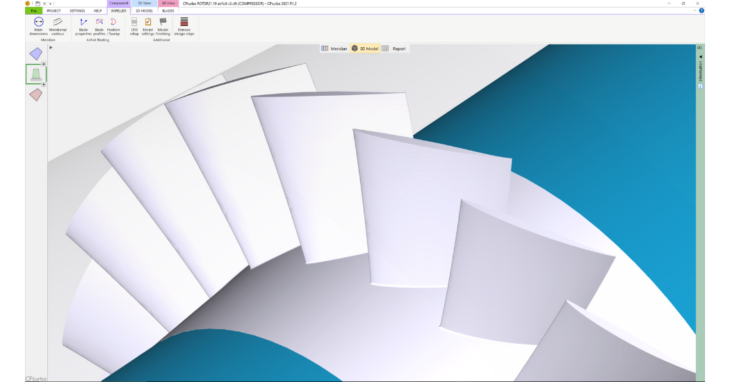
Now we can see the rotor in its actual state in our 3D-viewer. On the left side of the window, you have the model tree with all components and subcomponents.
This allows for easy navigation, renaming, and graphical adjustment. The user can modify color and translucency for each component, or subcomponent.
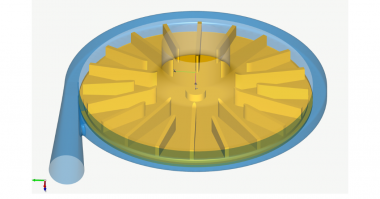
To prepare the CFD set-up first we add an inlet and an outlet extension. It is mainly needed for numericals reasons to minimize the influence of the boundary conditions to the flow in the rotor domain itself. For this purpose, we apply the “Stator” module of CFturbo which can be used to make vaned and un-vaned Turbomachinery components like pipes, or guide vanes. The inlet pipe should have a certain length in order to prevent an impact from the boundary conditions to the fan stage itself when running a flow simulation. The outlet domain is recommended to be even longer, due to the inherent swirl downstream of the rotor.
Just like in the previous design steps, the model can be shown and updated in our 3D viewer. The final design step would be “Model finishing” in CFturbo, include fillet design. Here will will set a fillet radius of 1 mm at the hub-to-blade intersection.
Model finishing means a geometrical operation to create solid models for the fluid domain and for the material domain in excellent quality.
This fishing is a pre-condition for many geometry export-formats. It will be used often, but not for all CAD or CFD-systems. For some codes export formats the model finishing will be done automatically.
Let’s save the model before we export the geometry and prepare the simulation, before we open the export window. CFturbo has export formats to neutral formats like IGES, STEP, STL, or ParaSolid, to all major CAD systems like Autocad Inventor, Catia, Creo, NX and Solidworks, and to nearly any commercial and OpenSource CFD Code that is capable running Turbomachinery simulations.
Solids models of the solid domain including blades and blade fillets, or vaned stator components can be exported into any CAD-format or meshing tool for CFD/CHT/FEA analysis. Direct export to rapid prototyping via STL is possible too.
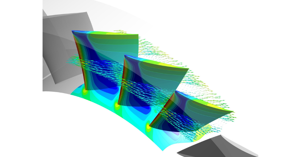
The geometry of the “CFturbo Rotor 21” an ongoing developed. There will be different derivatives to study performance, efficiency, shaft power, torque and transient flow patterns in the blade rows. For the CFD investigations we will use Ansys CFX. Results will be presented separately at a later date.
Please note that CFturbo is in general made for multi-stage axial compressor design, currently for up to five stages. As part of our general software development strategy we will continuously enhance the capabilities to empower Turbomachinery designers more and more. …
This slide gives an actual overview of important CFturbo export interfaces to CFD codes. The list will be extended if required.
There is a fully bi-directional integration of CFturbo into Ansys Workbench available. The parametric modeling of
CFturbo can be addressed for meshing, simulation, design exploration and optimization.
Additionally, Turbomachinery optimization workflows using CFturbo, Ansys CFX or Fluent and optiSLang can be easily established outside Ansys Workbench.
Design and CFD simulations can be highly automated running CFturbo in combination with SimericsMP, and any commercial or Open Source optimizer.
Putting CFturbo together with StarCCM+ and HEEDS – both products from SIEMENS PLM – does offer another excellent capability for Turbomachinery design exploration and optimizations
As you’ve seen, CFturbo is a user-friendly, straightforward tool for axial compressor design. To register for a free trial, and to learn more about our engineering services visit cfturbo.com
Comments