This video is about the conceptual design of an Axial, Single-Stage turbine as a component for a Cryogenic Rocket Turbopump.
Previously we had explained how to design a centrifugal pump, including inducer, impeller, diffuser, and volute, as shown on the left side. In this video, we will demonstrate the design of a single-stage axial turbine, which drives the rocket pump. To ensure a correct energy transmission, the shaft power and the rotational speed of both components must match.
At first, you create a new project choosing the turbine design module and insert the design point of the turbine. The design point, or duty point, is defined by mass flow rate, total pressure ratio, and rotational speed.
In our example, the fluid is liquid oxygen. In CFturbo, the CoolProp database can used to specify gases, liquids or mixtures. But it is possible to define any other fluid properties manually, if required.
Finally, we have to set the boundary conditions for the turbine, the inlet temperature, and the total inlet pressure.
And there is an option to specify the rotational direction of the turbine rotor. On the right side, you will see some essential physical values.
In this example, we will design a single-stage turbine made of a rotor and a nozzle. We start to design the rotor and running sequentially through all different design steps.
The user can choose between manual dimensioning or a supported design mode. Shrouded or unshrouded impellers can be created. For an unshrouded turbine rotor like in this example the blade tip clearance must be defined. Multistage machines can be made, if required.
CFturbo is driven by fundamental physical equations and numerous empirical correlations. These approximation functions are taken from textbooks, research papers, and our own data. With this, our code will be able to provide reasonable and detailed 3D-models.
Here we see design parameters to calculate the main dimensions of the rotor. A total-to static efficiency correlation is shown. All empirical correlations available in CFturbo can be edited manually by the user.
The proposed main dimension can be adjusted as well. On the right side of the window you can see important physical values of the rotor, a merdional contour, the Cordier diagram and initial velocity triangles.
In the meridional view, we adjust the axial length of the rotor, and we are defining the position and the shape of leading and trailing edges.
In this example, we use simple shapes for the leading and trailing edges and the meridional contour of the rotor. It will be straight lines with a constant z-value both for leading and trailing edge.
It is suggested to add a thickness of the hub solid to create a true geometrical solid later for export reasons. As shown, all Bezier points can be modified numerically by changing numbers in the pop-up window.
In general, CFturbo is very flexible creating complex shapes for hub and tip contours, as well as leakages, labyrinths and secondary flow path, if required. This capability of our software enables the direct geometry export from CFturbo to meshing tools, without another third-party 3D-CAD.
Next, we are designing the blade properties. In this window, at first, we define the number of blades as well as the number of spans. Then we select the blade shape for the turbine blades, and we define the blade thickness on leading, and on trailing edges. The blade thickness should be set manually by the user.
The user should estimate a slip factor for the rotor by angle or velocity ratio. According to CFturbo’s definition for turbines, a negative value should be applied. Using these parameters, blade angles on leading and trailing edges will be computed on every span.
An incidence angle can be defined, which will influence the blade angles on the leading edge of the rotor.
Then a method must be selected to calculate the radial equilibrium from hub to a shroud. The meridional and circumferential velocity components can be adjusted to balance pressure and centrifugal forces. In many cases, it is useful to choose the “variable load” option that enables you to shift the blade loading from hub to shroud.
Finally, CFturbo calculates the blade angles on leading and training edge on every span of the rotor blade.
On the right side of the window, there is a graphical representation of the velocity triangles, and we get additional, detailed information about all velocity components, beta distribution, and slip factor.
In mean line design, we determine the curvature of the blade between leading and trailing edges on every span. The wrap angle of the blade can be adjusted graphically or numerically. There are several diagrams to evaluate geometrical and physical properties, like relative velocity, blade loading, or static pressure.
In CFturbo, the user can choose between various methods of blade design. Currently we offer conformal mapping, direct modification of the beta-distribution, as well as “inverse design” method that is based on blade loading distribution.
In the final two design steps for the turbine rotor, we make the blade profiling or blade thickness distribution, and we round up the leading and the trailing edges.
There are three major design modes: linear interpolation, freeform, or loading an existing blade profile from the profile database. The spanwise profile distribution between hub and shroud can be handled flexible, or the user may set identic profiles on hub and shroud. Additionally, it is possible to make asymmetric leading and trailing edges.
On the right side of the window, there are diagrams to evaluate blade passage area, absolute and relative velocity, Mach numbers, blade loading, swirl and static pressure, among others.
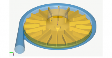
Switching to our 3D Model view, we can see the hub and blades of the turbine rotor as three- dimensional CAD geometry.
At this point we are ready to create the second component, which is the nozzle, a vaned stator upstream of the rotor. A vaned component that is located upstream of the turbine rotor creates the swirl, or rotational kinetic energy, that is needed to drive the rotor. Before we continue, we save the file.
Now we select the position and the type of component we want to add. Different stator shapes are available in CFturbo, for example freeform, axial, bowl or 90-degree bend. Here we select the axial type.
For the stator, at first, we must define its axial extension. This will be done by adjusting the overall nozzle length, or the position of hub and tip contour at the inlet of the nozzle. The length of the nozzle will be an input number. So far there are no empirical data available for this parameter.
On the right side of the window we see a schematic sketch of the meridional contour, however we also could display important physical and geometrical values of the nozzle.
The meridional design the stator is very similar to the axial rotor design. At first, we are defining the position and the shape of leading and trailing edges.
Again, we use simple shapes for the leading and trailing edges and the meridional contour of the rotor. It will be straight lines with a constant z-value both for leading and trailing edge.
As done before with the rotor, we add a thickness on hub and shroud to create a true geometrical solid later for export reasons. All Bezier points can be modified numerically by changing numbers in the pop-up window.
CFturbo would be very flexible creating complex shapes for hub and shroud contours, as well as leakages, labyrinths and secondary flow path, if required.
Now we can calculate the velocity triangles in the blade properties design window. In this window we define the number of blades as well as the blade shape, the blade thickness on leading and on trailing edges.
Here we have chosen 19 stator blades, and the blade shape will remain on “freeform 3D” as recommended for such type of impellers. Other blade shapes like “ruled surface” “radial elements” or “freeform 2D” would be available too.
The nozzle blade angles on leading and trailing edges can be set manually by the user on every span. Or, the trailing edge blade angle can computed based on inlet data of the rotor. For this, use the button: “Set alpha TE”.
On the right side of the window we have a graphical and numerical representation of the velocity triangles and the slip factor correlation diagram, among others.
In the next design step, we do the meanline design which determines the curvature of the blade between leading and trailing edges on every span.
The wrap angle of the blade can be adjusted graphically or numerically. On the right side of the window, we have several diagrams to evaluate geometrical and physical properties.
You can see plots and for relative and absolute velocity, pressure, swirl, and blade loading, among others. These calculations are based on “Stanitz-Prian” methodology. Here you see diagrams for the pressure-based blade loading, and the static pressure in blade-to-blade view.
The user can choose between several different design modes for mean line design like conformal mapping, blade angle progression, or blade loading definition.
To finalize the 3D-geometry of the nozzle, we have to make the blade profiling and to shape the leading and trailing edges.
For the blade profiles, we use a freeform thickness distribution on identic profiles at hub and shroud.
Leading and trailing edges were given an elliptic shape in our example, whereas the axis ratio of the trailing edge has been adjusted manually.
Now we can see both components, the nozzle, and the turbine rotor, in our 3D-viewer.
To finish the computational model, we add an additional flow domain upstream and downstream of the turbine stage. For this purpose, we add an axial stator on each side.
The non-rotating component should be given a certain length to avoid a negative impact of the boundary conditions to the turbine stage flow itself. It has to mainly be done for numerical reasons. In this case, we added a 25 mm pipe before the inlet of the nozzle, and a 75 mm pipe downstream of the rotor.
Since the 3D-viewer of CFturbo runs on a 3D-CAD-kernel, there are a large variety of display options, and numerous functions to create, to show and to check the geometry models. This fundamental functionality is beneficial later when it comes to CAD-export and batch-mode runs.
On the left side of the window, there is a model tree showing components and sub-components which allow easy navigation, renaming as well as adjusting color and translucency.
On the right side, we can see a window for information, warnings or error messages. It is linked directly to the online help manual of CFturbo.
The CFturbo “model finishing” enables the user to create and to export high-quality CAD solid models for export. During the model finishing process, one has the possibility to specify fillets on hub and shroud, if applicable.
For this model, we have build fillets on the hub and shroud of the nozzle and at the hub side of the rotor.
Compared to other conceptual Turbomachinery design tools, CFturbo allows a very detailed geometry representation of all significant components.
It is advantageous for direct export to CFD- or FEA-codes without applying another 3D-CAD system to prepare the computational domain. It is one of the pre-conditions for automated design exploration and simulation.
Now the model is prepared for a 3D-CFD-simulation. CFturbo has export formats to all major CFD-codes and CAD-systems and neutral formats like STEP, STL, or Parasolid. For this turbine example, we export the file to CFturbo SMP, also known as Simerics MP.
As shown here, there is a possibility to select settings for meshing and simulation. We’ve chosen mesh settings, which will create a mesh of about three million nodes. Mesh size can be adjusted and refined. It will become a hexahedral binary tree mesh.
In the solver settings window, we can choose between transient or steady-state simulation. For our demo, we use steady. The typical number of iterations should be five hundred to reach convergence. Additionally, we have the option to select a higher-order differencing scheme.
Export and meshing take about 10 minutes on a notebook with an Intel i7 processor.
We always recommend running 3D-CFD-simulations to evaluate geometry models designed in CFturbo. According to our experience, simplified methods like potential flow calculations, throughflow simulations, or loss-model-based performance curve estimations will not be sufficient for reliable feedback.
This rocket turbine example has been exported to SimericsMP for a CFD-simulation. Simerics MP is a modern, robust, fast, accurate, and cost-effective general-purpose 3D-Navier-Stokes code. CFD-simulations with Simerics MP provide realistic results that compare accurately with multiple field tests.
We import the results-file of a steady simulation using a multiple reference frame approach. This steady-state simulation example on a three-million-nodes mesh took twenty-four minutes on a laptop with an Intel I-7 processor. A fully-transient simulation with four revolutions would take about 90 minutes to converge for the same model on the same computer. Transient flow simulations usually provide higher accuracy compared to steady-state results, especially for off-design operating points.
Besides residuals, we can monitor physical properties and integral values like pressure ratio, efficiency, shaft power, torque, and volume flow rate, among others.
As you can see, the simulation results meeting the design goal in terms of the specified total pressure ratio (1.2) and the desired shaft power (1200 kW). The total-to-total efficiency values calculate as follows: 86% for the rotor and 75% for the full stage – excellent numbers for the first initial design.
As shown in this image, CFturbo has interfaces with numerous CFD-codes. All interfaces are under continuous improvement. The list will be extended if new codes or meshing tools enter the market.
In recent years it has become more and more affordable to combine Turbomachinery design software and CFD-codes with optimization algorithms. Here we see an example with CFturbo, ANSYS optiSlang, and Simerics MP. CFturbo can easily be adapted to various codes.
It is essential to create robust, automated workflows that allow user-friendly access for experts and beginners. For CFturbo, there is a bi-directional integration into Ansys Workbench available. ANSYS is, by far, the most widely used software for Turbomachinery CFD simulation, design exploration, and optimization.
As an alternative CFturbo works excellent with StarCCM+ and HEEDS, both products of SIEMENS PLM. This example shows an automated pump impeller optimization. There is general flexibility to run CFturbo in combination with any CFD- or FEA-solver and optimization software.
Try a free demo of our software today! https://cfturbo.com/software/download

Comments