This video is about the hydraulic design and CFD-simulation of a wastewater pump.
First you create a new project choosing the pump design module. In the global set-up the design point must be defined. The user must set volume flow rate, head, and rotational speed. Here the fluid is water. After choosing the design point, on the right side you’ll see the specific speed and the general machine type of the pump.
Now we add a new component, choosing the radial mixed-flow impeller option.
In this example, we will create a wastewater pump. Here, you have to choose the number of blades, which could be between one and three. We create an impeller with one blade.
To define the main dimensions of the impeller, CFturbo uses fundamental equations and empirical correlations. The user has the capability to use automatic mode, or to modify any of the main dimensions manually.
On the right side, you see a sketch of the meridional view and the Cordier diagram.
The next design step is to create the meridional contour of the impeller. Here we design the hub and shroud contour of the impeller, modify the axial length of the impeller and adjust the position of the leading edge, and – if required – we can define the position of the trailing edge too.
On the right side of the window, you see diagrams of static moment, cross section area, and meridional velocity, which comes from a potential flow calculation.
All Bezier points can be modified graphically or numerically. Here we see how the leading edge will be adjusted. The leading edge is a straight curve with a constant radius r=41 mm. Now we modify the hub nose by defining exact positions of the Bezier point. Finally, we reshape the hub contour by moving its central Bezier point.
Once the primary flow path design has been finished, we create the contours of hub and shroud.
Now we can add hub and shroud solids. For example, we can split the curves or transform them into Bezier splines. We can add Bezier points and merge curves. And we can define offsets to given curves of the flow domain. This tool is very flexible for modeling hub and shroud geometry. For demonstration purposes, we’re choosing a very simple model of the hub and shroud contour.
The description of hub and shroud contours will be part of the secondary flow path design which will be done later.
Hub and shroud solids, as well as blades can be exported later into any CAD-format or meshing tool for FEA analysis.
Please note: in the current version of CFturbo the solid domain modeling is not parametrized, compared to the fluid domains of the primary flow path, which are fully parametric, and which can be updated automatically.
Now we enter the blade property window, where we design blade angles on leading and on trailing edges. This is based on the Euler equation of turbomachinery. Additionally, we use slip factor correlations which help to determine the correct energy transmission.
Here the general blade shape is a “free form 2D” model which is typical for wastewater pumps. On all spans the blade angles will be computed and shown on the right.
The next design step is called meanline design. In this window we determine the wrap angle of the blade, and the blade curvature between leading and trailing edges, which has high impact on the performance of the impeller.
There are different design modes available, based on conformal mapping, or by setting beta progression directly. Meanline design will be followed by blade profiling and afterwards defining the shape of leading and trailing edges. The last two steps are just briefly touched.
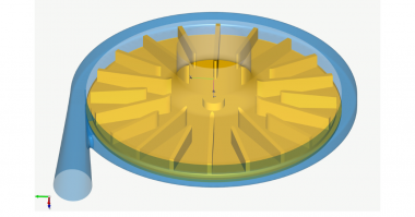
Here we see the model of the impeller in our 3D viewer. The orange sphere represents the minimum free throughflow diameter which is an essential design parameter for wastewater pumps.
Now we create the next component, which is the volute. For volute design we can select different cross sections like round, radius based, freeform, etc. all symmetric and asymmetric. The cross section shape can vary in circumferential direction as well.
There are different velocity-based design rules to calculate the extension of the spiral, for example the user can select between Pfleiderer- or Stepanoff- equations. Additionally, the user can create the spiral shape by their own geometrical requirements using the so-called geometry-based design mode. The influence of the cutwater thickness to the spiral shape can be considered by a correction factor.
The discharge diffuser could be radial, tangential or spline-based. Here we choose the radial version for the diffuser. We can adjust the length of the discharge diffuser as well as the discharge diameter, and – to some extent – the position of the diffuser in z-direction.
Finally, we create a fillet radius which represents the cutwater of the volute. Besides the fillet cutwater option the user can go for so-called “simple” or “sharp” cutwater design.
To prepare the CFD model we add an outlet extension downstream of the discharge diffuser. The outlet pipe should have an appropriate length in order to avoid a negative impact from the boundary conditions to the simulation results of the pump stage itself. We recommend an additional length of at least 5 times the discharge diffuser diameter.
In a similar way, the user should add a pipe on the suction side of the impeller. For this purpose, we add an axial stator. The stator should be given a certain length, and there must be a small gap between pipe and impeller in order to create the secondary flow path later. In this case we have added a 100 mm pipe at the inlet, and a 1mm gap between pipe and impeller.
Now we create a secondary flow path which describes the space around the impeller.
A precondition to creating the secondary flow path is the creation of the hub and shroud solids. The initial secondary flow path describes a simplified space which can be adjusted by drag-and-drop of Bezier points.
For this demo case, we’ve chosen a very simple shape. However, there’s high flexibility in shaping the space between the impeller and the casing. The corner points can be adjusted graphically or numerically. All lines can be transformed into Bezier splines.
For example, here we modify the casing contour near the eye of the impeller. This is very often used to design a small gap to minimize volumetric losses. In general, the shroud contour of the impeller can be adjusted accordingly. For example, the user can model a wear-ring, or a simplified labyrinth seal to prepare the CFD- geometry in CFturbo.
The model will be automatically updated in 3D, and we save it before we proceed.
The pump geometry is ready for export and simulation. We open the export window. CFturbo has export formats to all major CFD codes and CAD systems, as well as neutral formats like STEP, STL, or ParaSolid.
This model will be exported to SimericsMP. To export the model to SimericsMP, STL files are generated. We have to choose settings for meshing and simulation.
Our mesh settings will create a mesh of about one million nodes. Mesh size can be adjusted and refined. It will become a hexahedral binary tree mesh.
In the solver settings, we can choose between transient or steady state simulation, number of iterations or time steps and differencing scheme.
For our demo, we use steady and an upwind differencing scheme. In general, we recommend doing transient flow simulation with a higher order differencing scheme to reach an excellent level of accuracy in your predictions.
The user has the option to start meshing and CFD-software immediately, as it is shown here. SimericsMP starts and the meshing process will be finished after a few seconds.
Then the computational model will be generated, including its boundary conditions.
The computational model is prepared for simulation and boundary conditions are set for the design point. The project file will be saved before the CFD-simulation starts.
Besides residuals, we can observe the flow field in real time. Additionally, we’re able to monitor physical properties and integral values like head rise of impeller and stage, hydraulic efficiency of impeller and stage, shaft power, and torque. This steady state simulation would take about fifteen minutes on a laptop with an Intel I-7 processor. A fully transient simulation running four revolutions will take about one hour.
As mentioned before, we always recommend 3D-CFD-simulations to evaluate Pump geometry models designed within CFturbo.
In case design adjustments are necessary, after evaluating the simulation results, you can go back to CFturbo and modify the pump impeller or volute interactively. For example, you can change the main dimensions, blade angles, or volute contour.
Turbomachinery CFD-simulation codes like ANSYS-CFX, FINE/Turbo, StarCCM+, SimericsMP or TCFD allow cost-effective, accurate predictions of performance, hydraulic efficiency, shaft power, torque, NPSH and cavitation.
In recent years it has become more and more affordable to combine Turbomachinery design software and CFD-codes with optimization algorithms. It’s an exciting possibility for non-experts to create highly efficient pumps.
Here’s a 3D printed prototype of the pump impeller we just created! It was exported directly to a 3D printer from CFturbo. There’s no need to use an external CAD system.
For more information about our software, engineering services and training course, or to request a free trial, please visit our website cfturbo.com.

Comments