In this video, CFturbo be demonstrating a centrifugal pump design including a CFD simulation.
First you create a new project choosing the pump design module. Insert the design point of the pump. The design point is defined by volume flow rate, head, and rotational speed. In this case the fluid is water. On the right side, you’ll see the specific speed and the general machine type. Now we add a new component choosing the radial mixed flow impeller option. In this example, we will make a semi-automated design by clicking on the green check mark at the bottom of the window. By clicking the green check mark we complete the impeller design. Immediately we can see a 3D model of the blades and the hub and shroud contour.
In the meridional contour design window modifications of hub and shroud contours can be made as well as shaping repositioning of the leading edge. On the right side of the window there are diagrams for area progression, static moment, and curvature which can assist you in shaping the meridional contour of the impeller. All Bezier points can be modified numerically by changing numbers in the pop-up window. The user can adjust axial length of the impeller as well as shape and position of leading and trailing edges.
Now we add the hub and shroud solids. For example, we can split the curves or transform them into Bezier splines. For demonstration purposes we’re choosing a very simple model of the hub and shroud contour. This tool is very flexible for modeling hub and shroud geometry. The description of hub and shroud contours will be part of the secondary flow path design which will be done later.
Now we see hub and shroud model also in 3D. Hub and shroud solids as well as blades can be exported later into any CAD format or meshing tool for FEA analysis. The next module design step is to create a volute. Our volute modeling is fully parametric and versatile. Again, we choose a semi-automatic mode here to design a volute with a circular cross-section. Only minor adjustments to the discharge diffuser and to the cutwater will be done in this case.
First we modify the discharge diffuser design. The discharge diffuser will be made slightly longer and gets a different outlet diameter. The diffuser becomes a radial type instead of tangential. On the right side of the window we configure diagrams and control functions to modify the shape of the discharge diffuser.
For the cutwater, we create a fillet radius instead of the default simple cutwater design. We can modify the radius and the spiral start position. Another possibility for creating the cutwater design would be to create a sharp intersection between the volute and diffuser. The shape of the cutwater will be automatically updated in our 3D viewer.
To prepare the CFD model we add an outlet extension downstream of the discharge diffuser. The pipe should have an appropriate length in order to prevent an impact from the boundary conditions to the pump stage itself. In the same way we have to add a pipe on the suction side of the impeller. For this purpose we add an axial stator. The stator should have a certain length and there must be a small gap between pipe and impeller in order to create the secondary flow path later. Just like in the previous design steps the model is immediately shown and updated in our 3D viewer.
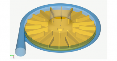
Now we create a secondary flow path which describes the space around the impeller. For this demo case we’ve chosen a very simple shape. However, there’s high flexibility in shaping the space between the impeller and the casing. A precondition to creating the secondary flow path is the creation of the hub and shroud solids. The initial secondary flow path describes a simplified space which can be adjusted by drag and drop of Bezier points. The corner points can be adjusted graphically or numerically. The lines can be transformed into Bezier splines. For example, we modify the casing contour near the eye of the impeller. This is very often used to design a small gap to minimize volumetric losses.
In general, the shroud contour of the impeller should be adjusted accordingly. Again our model is updated in the meridional and the 3D viewer. On the left side of the window you see the model tree with all components and sub-components of the pump. This allows for easy navigation, renaming, and graphical adjustment. We save the model before we go to export and simulation. CFturbo has export formats to all major CFD codes and CAD systems as well as neutral formats like STEP, STL or ParaSolid.
Now the pump is ready for export and simulation. We open the export window. This model will be exported to SimericsMP. We have to choose settings for meshing and simulation. We’ve chosen mesh settings which will create a mesh of about 1 million nodes Mesh size can be adjusted and refined. It will become a hexahedral binary tree mesh. In the solver settings we have to choose between transient or steady state simulation. For our demo we use steady. The typical number of iterations should be 500 to reach convergence. Additionally, we have the possibility to choose a higher order differencing scheme. To export the model to SimericsMP STL, files are generated. Then the computational model will be exported including boundary conditions.
The user has the option to start meshing and CFD software immediately as it is shown here. By choosing this option SimericsMP starts, and the meshing process will be done. SimericsMP is a fast, accurate and cost-effective general-purpose 3D Navier-Stokes solver. CFD simulations with SimericsMP provide realistic results that compare accurately with multiple field tests on various types of rotating machinery like pumps, blowers, compressors and turbines.
Now the model is ready for simulation. The boundary conditions are set for the design point. For this initial run we deactivate the cavitation module. The project file will be saved before the simulation starts. Alternatively to starting the simulation manual as shown here, batch mode runs can be prepared to run performance curves or maps. Besides residuals we can observe the flow field in real time. Additionally, we’re able to monitor physical properties and integral values like head rise of impeller and stage, hydraulic efficiency of impeller and stage, shaft power, and torque.
This steady state simulation would take about 15 minutes on a Dell laptop with an intel i7 processor. A fully transient simulation simulating 4 revolutions will take about one hour. For models with larger mesh sizes, there are options for distributed parallel computing available to fulfill higher computational requirements. We see here a converged solution for the steady state simulation.
We always recommend doing transient flow simulation to get a higher level of accuracy in your predictions. In case design adjustments are necessary, after evaluating the simulation results, you can go back to CFturbo and modify the pump impeller or volute interactively. For example, you can change the main dimensions, blade angles, or volute contour.
Comments