Identifying and Correcting BBBB Conditions on Installed Machinery
BBBB conditions normally occur on machines that have been installed for some time, and for a variety of reasons:
- No alignment, or improper alignment, before the machine was installed.
- Process or equipment changes, which mean that original machine components, such as motors and pumps, have been switched over to different models, larger horsepower demands, piping changes, etc. These changes are sometimes done on existing baseplates or skids, without considering that the heights of the new components may be different.
- Thermal changes in piping, which can cause unwanted piping movement.
- Foundation or grout settling, or machinery base degradation.
- Improper use of pipe hangers, saddles, conduit, flexible flanges, or other external devices mounted to the system.
Regardless of the cause, shaft alignment may never be satisfactory until the problem is remedied.
There are a several methods to correct a BBBB condition. Some are quite simple and easy to employ. Others may require extensive reworking of the machine base. If such a condition is measured, make the following observations:
Base Bound
|
Bolt Bound
|
These methods can be employed to correct a BBBB condition with a minimum of work.
Correcting Graphically
If the condition is slight to moderate, AND if a slight movement of the stationary machine is possible (without inducing pipe or duct strain), it is possible to graph the misalignment, determine alternative moves, and correct the misalignment.
| In this example, vertical misalignment is:
|
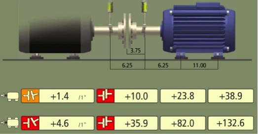 |
The vertical misalignment may be solved using the following steps:
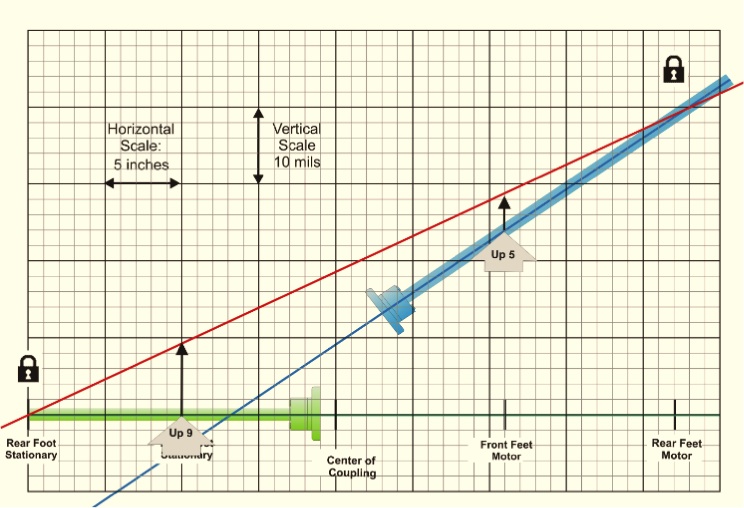
- A straight line, representing the vertical centerline of the stationary shaft (a side view), is drawn (shown in black).
- Positions of the movable and stationary machines are labeled and graphed as follows:
- RFM=Rear Foot Moveable
- FFM=Front Foot Moveable
- COC=Center of Coupling. Think of this as the “pivot point” between the machines
- FFS= Front Foot Stationary
- RFS= Rear Foot Stationary
- The misalignment correction amounts for the movable feet are plotted.
- A line (shown in red) is drawn connecting the correction amounts at the feet, and it projected to the stationary machine.
- A line is drawn connecting the Rear Foot Movable and the Rear Foot Stationary (shown in green).
- By using the vertical scale of 10 mils per block, we can calculate the moves needed to correct.
- Shim the Front Foot Stationary up 10 mils.
- Shim the Front Foot Moveable up 5 mils.
Correcting Mathematically
| In the same example, the Rear Foot Moveable is +38.9 mils, the Front Foot Moveable is +23.8 mils, and the distance between them is 11 inches. From this, we can calculate the slope:
38.9-23.8 / 11 = 1.37 mils/inch
This is the slope the moveable machine has. However, the slope we want is the slope from the Rear Foot Moveable to the Rear Foot Stationary, using the Rear Foot Stationary as a zero point.
38.9 mils/42 inches = 0.92 mils/inch
So, measuring from the zero point (Rear Foot Stationary) to the Front Foot Stationary:
|
|
|
10 inches x .92 mils/inch = 9.2 mils of shim added to this foot.
Measuring from the zero point (Rear Foot Stationary) to the Front Foot Moveable:
31 inches x .92 mils/inch = 28.52 mils (minus the 23.8 mils it already has) = 4.72 mils added to this foot.
These results are close to the results plotting in the graphical method, but since they are done mathematically, they are calculated to a degree of accuracy that is difficult to do graphically. The only errors would be in the degree of measuring, the amount of “rounding off” the numbers, and the accuracy of performing the calculations.
Correcting With the Laser Alignment Tool
| The Feet Lock™ function in the Fixturlaser XA systems allows the user to easily identify the moves necessary on the stationary and movable machines. Several solutions can be examined very quickly to determine which move is most appropriate. Other alignment tools offer similar methods.
The benefits of using an XA System to correct this condition are:
|
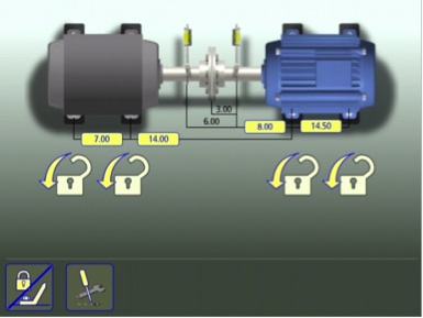 |
- Using Live Mode, you can see the correction values in real time, and make any further corrections necessary to achieve an accurate alignment.
- The user can choose which combination of “feet” to move, even alternating between machines.
Correcting By Modification
If none of these options will move the machines sufficiently to correct BBBB, there are other alternatives. They require more work, usually are more expensive, and often must be approved by engineering.
- Use undercut bolts, or smaller bolts.
- Slot the base.
- Oversize the holes in the motor feet.
- Plug the existing holes in the base, and re-drill and tap new ones in the proper location.
- Use a portable milling machine to remove material from the baseplate. Grinding by hand is not recommended, since it is difficult to grind the surface flat enough.
These should be your last options, because they usually require much more work and downtime.
Summary
The best time to correct a Base Bound or Bolt Bound condition is when the machine is new, and before it is installed. The next best time is during the installation process, before any additional components, such as piping or conduit, as mounted.
If Base Bound or Bolt Bound conditions are encountered on existing equipment, there may be options to expensive re-machining and re-work.
Lastly, there are options to solving for Base Bound or Bolt Bound conditions. And the more accurately and easily they can be performed, the more accurate the alignment results will be.


Comments