We were recently discussing how a constant volume heating, ventilation and air conditioning (HVAC) system would continually pump the same flow rate of chilled water through the entire system regardless of the cooling load. This worked well when maximum cooling was needed on a hot day, but during times of low cooling load, much of the chilled water would go through the bypass. This method allowed the system to be controlled, but at a high cost. Also discussed was how centrifugal pumps connected to variable speed drives (VSD) could be used to reduce the pumping cost in a chilled water system by varying the flow rate through the system to match the system’s cooling loads.
A New System
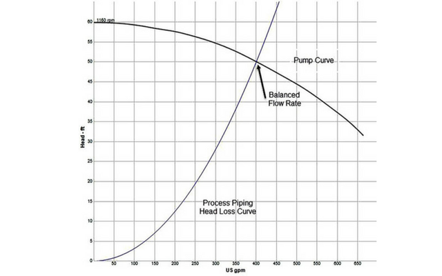
Since HVAC systems are recirculating systems, there is no static head for the pump to overcome. As a result, the pump simply needs to make up the head loss associated with the flow through the interconnecting pipelines and the air handlers. The head loss in a closed system can be simplified by graphing the head loss versus the flow rate (see Figure 1). By superimposing head loss curve on the pump curve, one can see how the system can work together. The flow rate through the system occurs at the intersection of the pump and head loss curves.
By installing a VSD on the pump, the pump’s speed can be adjusted so the system flow rate can be matched to the flow rate required for the system heat load. Using this approach, the flow rate through the system can be controlled by adjusting the speed of the pump using the VSD.
In chilled water systems, a design temperature drop is established for the heat exchangers in the air handlers. The flow rate through the air handlers is adjusted so the air outlet temperature of the air handler equals the temperature set on the occupied space thermostat. If the temperature of the occupied space is too high, the chilled water flow through the air handler is increased. When the temperature of the space is below the set value, the chilled water flow rate through the air handler is decreased.
Now let’s see what happens when the thermal load of the space is only 50 percent of the designed heat load. Since the heat load of the space is only 50 percent of the design value, the chilled water flow rate through the air handler only needs to be 50 percent of what is needed.
This causes the pump to operate back on the pump curve, resulting in greater discharge pressure. As a result, the differential pressure across the temperature control valves is higher at lower flow rates.
In HVAC systems, with the large number of cooling circuits, air handlers and temperature control valves, the system must be designed to minimize pressure drop across the temperature control valves. This is why constant volume systems are still widely used in HVAC chilled water systems.
Constant Flow Systems
In a constant volume system the flow rate through the system is maintained at a constant flow rate regardless of the system’s thermal heat load. The space room temperature is maintained by bypassing some of the chilled water around the air handler. In our example, 50 percent of the design flow rate will pass through the heat exchanger with the remainder bypassing the heat exchanger. Once the system is balanced, the differential pressure across the temperature control valve can remain at a low value under a variety of flow rates. Since the chilled water flow rate through the system must meet the system’s highest thermal load regardless of the current thermal load needed to meet the operating conditions, this will control the system but at a higher pumping cost.
Variable Volume Systems
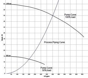
In a variable volume system, only the chilled water needed to meet the thermal load passes through the system. Without a variable speed pump, the temperature control valves in each circuit are not large enough to accompany the higher differential pressure required. Figure 2 shows what happens when operating the system at 50 percent of the thermal cooling load.
Using a pump with a VSD installed, the rotational speed of the pump is adjusted so the pump curve intersects the head loss curve at the 50 percent flow condition. Not only is the pump passing only 50 percent of the design flow rate, but the system requires less head at the flow rates. This reduction in pump head and flow rates results in a tremendous energy savings.
Looking at how a pump with a VSD installed saves energy, building owners were installing them on their chilled water systems. This was successful when installing VSDs on new systems, usually HVAC chilled water systems, but there were problems when installing them in existing systems.
Installing VSDs in Existing Systems
Many building owners were looking at installing VSDs on chilled water pumps in existing systems. This is where problems started occurring. Looking at the simplified curve in Figure 1, the head loss in the system is represented as a single loss curve, which in reality consists of multiple loops working together. Each circuit is supplied by the common pump, but each path has head losses associated with the interconnecting pipelines, air handlers and a control valve. The outlet temperature of the air handler is adjusted by controlling the flow rate through the circuit.
In HVAC systems, there are many control valves needed for the various circuits. The temperature control valves are sized with low differential pressures to keep the cost of the valve actuators down and minimize the airborne noise associated with a high pressure drop. If the differential pressure across a temperature control valve is too great, the circuit will not operate properly.
When converting an existing constant volume system to a variable volume, or when adding cooling loads to existing systems, many of the control valves show excessive differential pressure. However, there are ways to overcome the problems associated with high differential pressure to take advantage of the VSD savings. They include installing and setting balancing valves in circuits with high differential pressures, installing differential pressure controllers to minimize differential pressures across temperature control valves or installing pressure independent control valves.
Installing Balancing Valves
Manual balancing valves can be installed upstream of the temperature control valves. The balancing valves are manually set to pick up some of the circuit head loss, resulting in minimizing the head loss on the temperature control valve. This requires installing and setting the balancing valves for each circuit in the system. Any time the thermal load in a circuit or system changes significantly, the system must be rebalanced to meet the design changes.
Installing Flow Limiting Regulators
A variable volume system can be designed by installing flow limiting regulators upstream of the temperature control valves set to the circuit’s maximum flow rate. In our example, let’s assume a maximum flow rate through the cooling circuit is 50 gallons per minute (gpm) and a flow limiting regulator is installed upstream of the temperature control valve. The flow limiting regulator will not allow more than the set value regardless of the inlet pressure. The flow limiting regulator also results in head loss at the lower flow rate, much like a manual balancing valve (as described above) thus reducing the differential pressure across the temperature control valve.
This approach eliminated the need to balance the system when changing the thermal loads on other circuits in the system, but the valve must be replaced when increasing the head load on the affected circuit.
Installing Differential Pressure Controllers
As the number of circuits in an HVAC system increases, the differential pressure across the temperature control valve increases as well. This is especially true across the circuits physically closer to the pump.
In HVAC chilled water systems, the pumps provide all the hydraulic energy needed for each circuit within the system. The circuits physically located closest to the pump have less head loss in the interconnecting piping than the circuits located farther away from the pump. As a result, the circuits closest to the pump typically have a much higher differential pressure across the circuits than the heat loads located farther from the pump.
The use of a differential pressure controller senses the pressure at the supply and discharge headers across the circuits (see Figure 3). The differential pressure controller positions the regulator to absorb the excessive hydraulic energy across the supply and return header, thus allowing the temperature control valves to operate properly. This approach requires the installation of the differential pressure controller along with the connections for the pressure sensors. Since the differential pressure of a circuit or a group of circuits supplied by a common supply and discharge header is maintained at a set differential pressure regardless of flow rate, the associated temperature control valves will be easier to control.
The disadvantage to this approach is potential overloading if there are too many circuits supplied by a given differential pressure controller.
Installing Pressure Independent Controllers
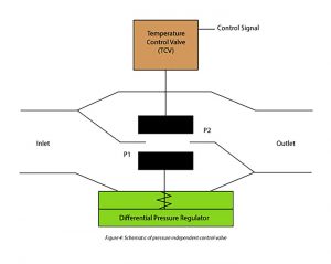
Pressure independent controllers (PICs) can successfully regulate the flow rate through the temperature control valve with a wide range of differential pressure. This is accomplished by installing a differential pressure regulator (DPR) in the same valve body with the temperature control valve.
The DPR uses internal passages to set the differential pressure across the temperature control valves to a constant differential pressure regardless of the flow rate through the valve.
For example, assume there is a 40 psi pressure drop across the PIC. The temperature control valve is supplied an input signal to regulate the flow rate through the valve to the air handler. The downstream fluid pressure of the temperature control valve is measured at location P1 within the valve. The pressure at location P1 is automatically regulated by the DPR to maintain a constant differential pressure of 5 psig regardless of the flow. The position of the DPR valves inlet pressure is supplied to the DPR section of the valve. In this example the DPR positions the valve stem to provide 35 psig.
When the circuit requires reduced flow, the differential pressure across the PIC increases. The integrated pressure regulator adjusts to increase the head loss for the required flow rate, and the temperature control valves sees the same five psi differential pressure. The differential pressure regulator can absorb the excess head regardless of the flow rate required by the circuit.
Since the temperature control valve always sees a constant differential pressure of five psi, the valve the circuit is able to able to operate properly under a wider range of cooling loads and differential pressures.
PICs must be purchased and installed in each circuit for the system to operate properly. They cost more than a standard control valve, but are not affected by differential pressure across the circuit, so there is no need to install balancing valves, flow limiting valves or differential pressure controllers. In addition, by maintaining a constant differential pressure across the temperature control valve, regardless of chilled water flow rate, the system can be controlled with a varying thermal load.
Integrating the VSD into the System Control
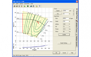
Installing a VSD on a pump in an HVAC chilled water system allows us to vary the pump speed to regulate the flow rate through the system to meet the system thermal loads. The VSD is controlled to maintain sufficient pressure, so the pump can provide the flow to all circuits to meet the system’s thermal loads. Choosing the location of the pressure source used to supply the control input can be simplified by using simulation software to model the entire piping system so one can see how the system will operate under any expected operating conditions.


Comments