Author: Michael Huebner, Principal Engineer, Flowserve
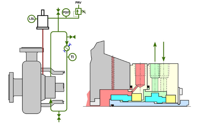
Arrangement 3 seals contain two mechanical seals in a cartridge assembly with a pressurized barrier fluid in the cavity between the seals. This arrangement, also known as a dual pressurized seal or double seal, provides a range of benefits including eliminating process leakage to the environment, greater tolerance for upset conditions in the pump, and the ability to monitor seal performance (see Figure 1 above).
There are a number of standardized strategies (or piping plans) to provide the pressurized barrier fluid and these are defined in API 682. One of these strategies, a Plan 53C, utilizes a piston accumulator to pressurize the system. The bottom of the accumulator is connected to a reference pressure in the pump. This is most often the process fluid in the seal chamber since it provides the most relevant pressure for the seals. The top of the accumulator is connected to the Plan 53C barrier fluid system.
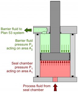
Figure 2 Piston accumulator
The piston accumulator operates on a principle of pressures and areas. The accumulator has differential areas on the reference pressure side and the barrier fluid sides of the piston. The ratio of these areas produces a correspondingly higher pressure in the barrier fluid.
There are several benefits of a Plan 53C system. The piston accumulator is self-energizing and will automatically pressurize the barrier fluid as the pump is commissioned. The system is self-tracking and will allow the barrier fluid pressure to compensate for changing pressures in the pump. Finally, the system can be designed so that it does not require any external utilities which makes it ideal for remote locations.
The piston accumulator also introduces a few disadvantages. The connection to the seal chamber introduces process fluid into the accumulator. The piston in the accumulator must also be free to slide in the bore of the accumulator to track pressure and compensate for barrier fluid leakage. This makes this piping plan most appropriate for clean fluids which are free from solids or contamination which cause the piston to hang-up.
Another problem seen in the field with this system is caused directly by the operators maintaining the barrier fluid level in the system. As barrier fluid leaks past the seals, the piston will slide upwards to compensate for the fluid loss. Before the piston reaches the top of the accumulator, the system will alarm on a low barrier fluid level. The operator must add barrier fluid to replenish the lost fluid and allow the system to continue operating. The volume between the minimum and maximum barrier fluid levels represents the working volume of the accumulator.
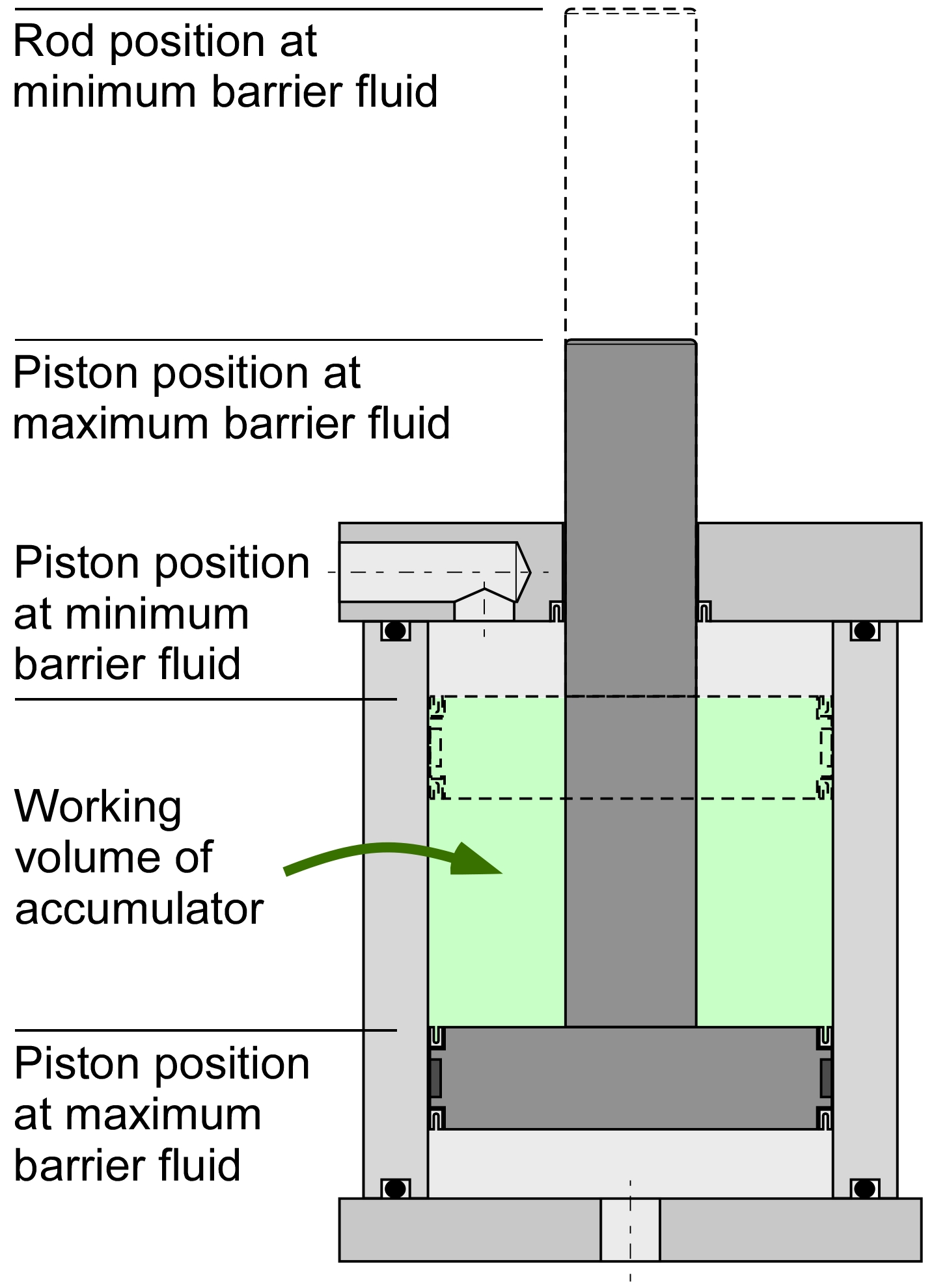
Figure 3 Working volume of accumulator
Problems can occur when the operator adds fluid. If too much barrier fluid is added to the system, either at initial commissioning or during maintenance, the piston can be forced down to the bottom of the accumulator. When the piston bottoms out, it will no longer be free to slide and maintain the correct pressure. If the temperature of the barrier fluid increases, the thermal expansion of the fluid will create a runaway pressure increase which will result in seal failure, damage to the piston accumulator, or rupture of the system.
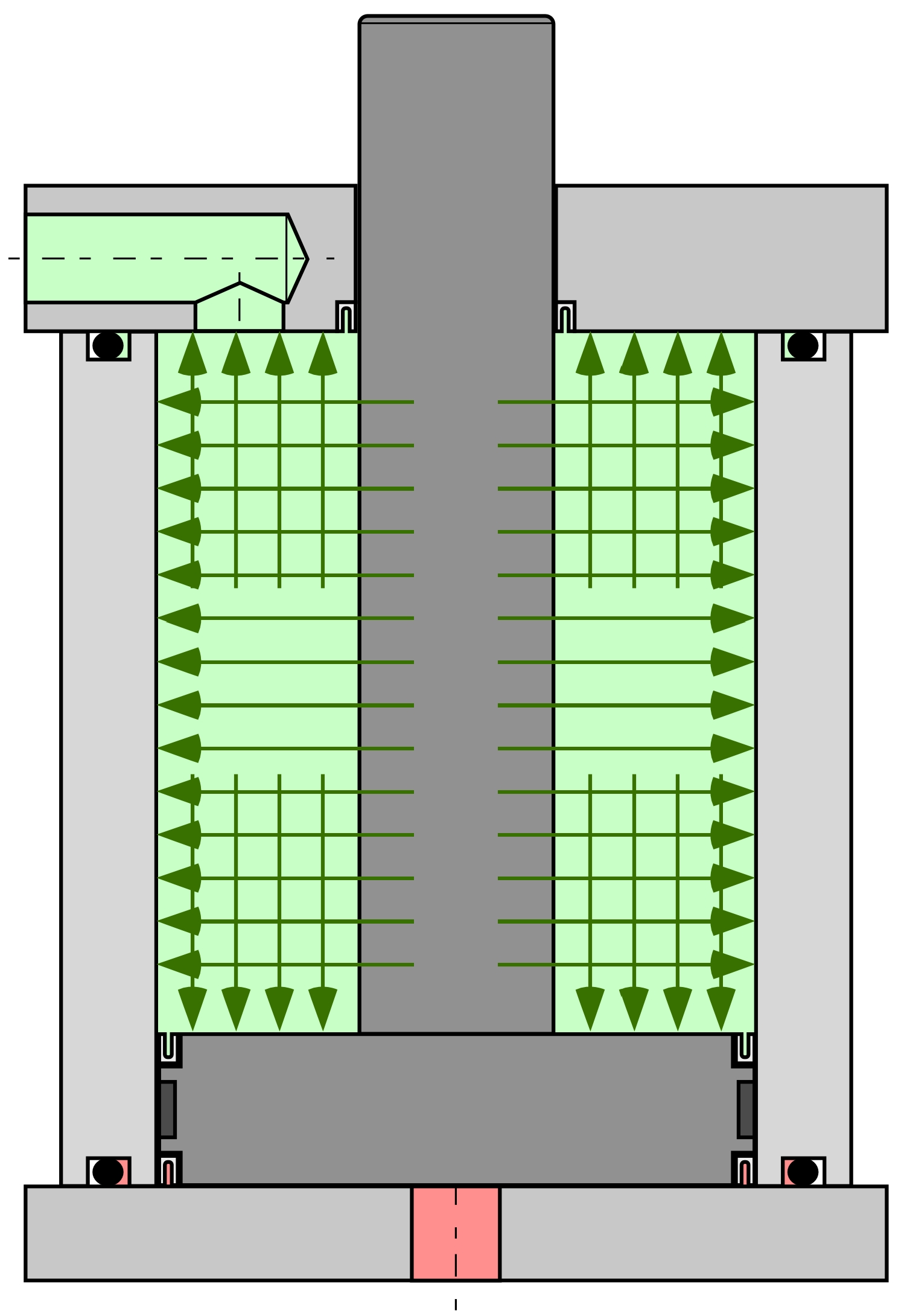
Figure 4 Overfilled accumulator
The primary way to prevent this from occurring is to understand the operation of the system and how it should be maintained. The piston accumulators should have markings to indicate the proper fill level. Adding additional fluid beyond the “Full” marking is never recommended. To help protect against over-pressurization, a pressure relief valve can be added to the barrier fluid side of the system. While this relief valve can provide some protection, it introduces additional problems and can lead to a loss of containment. The primary approach to proper operation must be to properly maintain the system and avoid overfilling the piston accumulator.
Comments