Intro
When a pump goes down, it never seems to be at a convenient time. In the middle of the night, during a rain storm, during a high level event, it is important to figure out the cause of the issue as quickly as possible. For pumps in service which have either tripped a breaker or have a high amp measurement, this article will provide a series of checks that can be performed to identify the cause of the malfunction, and help to get the station back online.
Procedure
It is recommended the following be done on-site prior to pulling the pump.
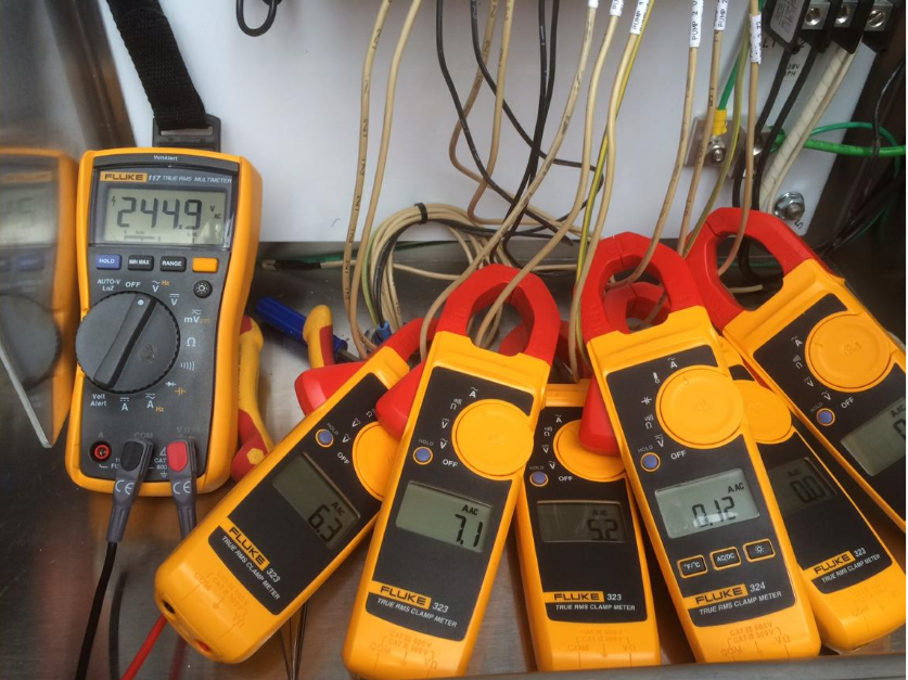
- Measure and record supply voltage and amp reading and compare to start-up information and recently collected data.
- Measure and record performance data from the operational pump if this is a duplex or triplex station
- Perform Megohm test on-site if possible to determine stator and power lead condition. If this test does not indicate a short or an open winding, proceed to the next step, # 4 below. If stator does not pass these electrical tests, then proceed to the following step, # 5 below.
- If possible, switch power leads and determine if problem follows the pump. If problem stays with the supply, the pump is not causing the problem but may require inspection if operated for a long period with faulty supply.
- If problem follows the pump, it is recommended the pump be pulled from service following all safety precautions, as outlined in the applicable codes and instruction manuals, and brought to a suitable shop for repair.
The following is a recommended outline of inspections to determine the scope and nature of problem.
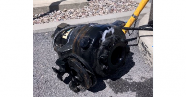
- Visually inspect pump, cable, and suction and discharge ports for any sign of problems. Proceed if there are no obvious problems.
- If cable does not have noticeable cuts or abrasion, feel for signs of water intrusion. Cable will generally be slightly enlarged and will be more compressible or spongy. It is best to have a new cable on hand to compare with. If there are no signs of water, proceed to step 3. If there are signs of water skip to step 5.
- Remove a small sample of seal oil. Take care not to spill any oil. This oil should be clear and free of any signs of water or contaminants. If water is present, the oil will appear milky in color. If this oil is clean, proceed to step 5. The seal oil will become contaminated with water under normal circumstances. If this occurs without any indication of stator problems, this oil can be changed and the pump placed back in service. If there are noted electrical problems as well as signs of water in the oil, it is likely the seals have become damaged and moisture has migrated up into stator. The pump will likely require a complete tear down.
- If seal oil appears clean, replace the plug and return pump to an upright position.
- Inspect the junction chamber or terminal board, if the pump is equipped with one, for signs of water intrusion and or stator damage.
- The source of water must be determined. Explore each step below. If there is no sign of water intrusion in either the seal chamber or junction chamber, proceed to step 10 below.
- If water is present in the junction chamber and the seal oil was clean, the power cord was the most likely source of water. Remove cable and inspect. Make a cut parallel to cable conductors and inspect the internal region of the cable. If water is present or there is a brownish residue, the cable has been wet.
- Inspect further to determine source of water. The grommet or o-ring used to seal the cable at the entry point should be evenly compressed with no signs of wrinkling or uneven distortion. The point of contact of the cable and grommet should also be evenly compressed with no visible signs of uneven compression. If there are no signs of water entry at the cable entry and the seal oil is clean, the likely source of water is through the whole length of cable.
- Further inspection of the cable will generally show signs of moisture throughout the entire cable. The installation site must now be inspected for possible causes of the water damage. “J” boxes in the wet well and improperly sealed control panels or junction boxes are likely sources of the water.
- If the cause of the stator failure is not water damage and the seal oil is clean, there have been one or more electrical supply events that have occurred and caused damage. The cause of the problem must be determined, explore each step below. Further disassembly of the pump will be necessary for some of the inspections below.
- Remove the power cables and perform the Meg-Ohm test again. If this test is OK, the power cables may be replaced and pump re-tested for service. If the stator fails the Meg Ohm test, further investigation of the stator is required. Continue with the steps below.
- Inspect the interior portions of the stator for small signs of a burnt area. Small localized areas, in an asymmetrical fashion in one location generally indicate a failure of the winding. If the pump is new and has operated for a period of less than 15 days, this is generally considered a warranty failure. Contact the pump supplier and be prepared to provide evidence of equipment failure.
- A large, localized, asymmetrical, burnt area in one location generally indicates a power surge. This will discolor a large portion of a stator but not entirely. The cause of this failure needs to be determined.
- If the stator is in generally good conditions with certain windings discolored and damaged in a symmetrical fashion this indicates a failure of the power supply. In a three phase motor, this will occur if there is a loss of one leg of power or if there is an unbalanced power supply. The site supply must be investigated to determine cause of failure and corrective action necessary to prevent further damage to the pump.
- If the stator has all of the windings discolored and excessive heat is noted by melted winding ties, there has been an overload of the motor. Inspection of the bearing grease is necessary to determine if the pump was operating or if there was a locked rotor situation.
- In an overheat situation where the pump was still able to run, inspection of the bearings would show the bearing grease turned into a dark, pasty consistency. Additionally in severe situations, the rotor would be melted and the aluminum would be flung away from the center of the rotor, this would indicate the pump had been over heating for an extended period. This can be caused by several operating conditions, such as a loss of cooling from inoperable float switches in a locked rotor situation. Proper installation of the motor thermals will limit the amount of damage to the pump.
- In an overheat situation where the pump is not able to turn, the failure is usually quicker and bearing grease may not be affected. In this situation, the rotor will be heavily “blued” and the melted aluminum will have run down the rotor.
Comments