When a pump goes down in wastewater applications a common misconception is that the pump is always the source of the problem. Many if not most times, a system’s impact on the pump or other external environmental/operational factors are the reason for pump failures occurring.
Pumps are only one part of a system consisting of many parts that impact their operation, and continually repairing failed pumps without determining the root cause of the failure is all too common. Doing so can be very expensive over time, and it can also lead to stressful situations. In the common duplex pump station scenario, for example, a downed pump can cause much concern because with one pump down, the single remaining pump is all that stands between an operational station and a potential sewage overflow.
With pumps so critical to wastewater systems, it is wise to perform more system troubleshooting on unusual or repetitive failures to find and solve the root cause issue(s) that negatively impact the system. Beyond the assumption that the pump is the problem, operators or maintenance staff may simply feel there isn’t enough time or resources to dig deeper into problems.
Getting to the heart of issues is likely less expensive and time-consuming than one might think, and good distributors who supplied the original equipment and the manufacturers’ applications engineering/service staff that support them are excellent resources available to assist with this or to provide guidance.
This starts by investigating symptoms such as abnormal noises and strange episodes of electrical trips, etc., that may accompany recurring pump failures. It is possible to troubleshoot issues, or at least narrow down a problem to make a more targeted service call, by examining key indicators and asking the right questions.
Getting Started
The root causes of pump failures generally fall under one of two categories – electrical or mechanical.
Poor-quality power can lead to pump/motor failures, so begin by taking power readings. Are the voltage and amperage values within normal range, and are they balanced between phases, etc.? Voltage unbalance between phases on the supply side will cause a disproportionately high current unbalance and motor temperature rise, shortening motor life; a 1% voltage unbalance can create a current unbalance in the range of 6-10%, and with a 3% voltage unbalance, the resulting motor temperature rise is increased by up to 18%. Voltage supply unbalance can be caused by uneven single-phase loads on the three-phase grid, commonly found in areas where residential single-phase air conditioning loads are prevalent. Also, voltage drop and the corresponding current increase from being installed long distances from the transformer can have a negative impact, as can a variety of factors arising from the use of variable frequency drives. See the section on VFDs below.
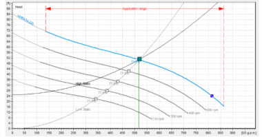
For mechanical or performance issues, and also to determine potentially why the motor current or input power is high, it is critical to know where the pump is operating on its curve. The operational “duty point” of the pump is the intersection of the system curve and the pump curve. In the design phase, the system curve of the pump discharge piping and force main is typically calculated with some conservatism built-in. Over time, the actual system curve can change due to things like sedimentation buildup in the piping, air entrainment at piping high points, scale buildup on pipe walls, etc. Older stations may have been sized based on an anticipated increased future capacity that may or may not has come to pass. Unfortunately, it is not uncommon for new equipment retrofits of older stations to be selected based on the original system curve and design pump duty point, which, in reality, maybe far from the actual conditions, resulting in an incorrectly sized pump.
Flowmeter readings, if available, are optimal to determine the actual flow rate of the pump in the system and allows the pump and actual system curves to be plotted, showing where the pump is running compared to the design conditions. If a flow meter is not available, a drawdown test can be used to determine the flow rate of the pump. A drawdown test is performed by first calculating the volume of the sump as a function of sump level, then recording the amount of time it takes to fill the sump between two specific sump levels (inflow). Then, after the sump fills, recording the time to pump down to a specific elevation. Measuring over a smaller range – 1 to 2’ range is typically preferred, since a shorter duration generally ensures that the inflow remains somewhat constant. Applying the formula [Pump Flow = Gallons/Minute Inflow + Gallons/Minute Pump Down] provides a reasonable pump flow rate measurement.
In many failure cases, the pump isn’t operating within specifications, so determining actual pump flow offers an insight to pump health and may provide clues to problems, such as the pump running off its curve or outside the prescribed Acceptable Operating Range (AOR), where recirculation cavitation and/or excessive vibration may occur. Pressure measurements from a pressure gauge on the discharge line corrected back to the pump discharge elevation are also valuable for determining where the pump is operating.
Once there is a low-flow indication, dig deeper by running down this checklist:
- Is there more head on the pump than was originally designed?
- Is the check valve not opening all the way?
- Is there cavitation (low-pressure condition where the liquid turns into a vapor at the eye of the pump impeller) due to inadequate Net-Positive Suction Head Available (NPSHA)?
- Is there enough NPSHA at the site compared to pump requirements?
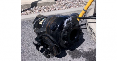
- Is the impeller showing premature wear?
- Is there a clog in the piping?
- Is air entrainment occurring from cascading flows in the sump?
- Does the measured flow and pressure correspond to the pump curve? If not, look for unanticipated inlet losses.
If you’ve checked out the basics above but still have not identified a definitive problem, consider diagnostic testing. A full-service testing organization will be able to bring equipment to your site that measures power quality and can dig deeper into mechanical problems by performing vibration testing and other tests.
VFDs Can Also Present Problems
Variable frequency drives (VFDs) are popular because they allow for a range of flows by varying the pump curve though speed regulation, perform as soft starts for a gentler ramp-up avoiding the high initial motor inrush currents, and allow. However, VFDs present their own set of issues that can lead to pump failures.
Some common VFD-related issues include low operational speed. If the pump is oversized, or if the duty point is based on maximum station inflow conditions, then the majority of its operation may be at reduced speed. In those cases, it is critical that the minimum speed setting is set such that the flow velocity through the piping system is high enough to prevent sedimentation from settling out and that enough pressure is generated to be able to overcome the static head. If the wastewater is heavily concentrated with rags or stringy materials, low-speed operation can cause rag balls or fouling buildup to form in the eye of the impeller, which can lead to a multitude of problems. Consider ramping the pump speed up to full speed operation for a short period upon start-up and shutdown, in this case, to “flush” the pump at the beginning and end of its pumping cycle.
There are several factors with VFD use such as length of cable, cable size, and type of VFD that can cause voltage distortion in the form of spikes or harmonics which can destroy the motor stator, or cause common-mode voltages and shaft voltages which result in bearing currents. Bearing currents create heat and degrade bearing grease and races, potentially causing catastrophic failure. In such cases, sine wave filter, or dV/dT filter may be required.
There are many system and operational/environmental aspects of a pump application that can lead to pump failures in wastewater applications, so fixing repeat failures without digging deeper is a substandard approach. For long-term operational security and savings, it is best to investigate and cure the root cause.
Originally Published on Water Online
Comments