Monitoring the load on the motor that is driving a machine or process can give you valuable information since this motor reflects the changes that are going on.
On a mixer or agitator, for example, as the viscosity increases, it will take more power to stir the mixture and when it thins the load goes down. When cutting metal, as a tool gets dull, it takes more power to make the cut. And, when a pump runs dry, the load drops off sharply.
Here are a few other applications:
- Monitor Pump or Fan Flow
- Sense the Beginning or End of a Process
- Control Optimum Feed Rate
- Sense Overload
- Loss of Load
A power sensor can measure these load changes and send a signal to meters, computers, programmable controllers, recorders or data collection systems. A load control senses the load and has built-in relays to sound alarms, change feed rates, stop the machine, etc.
Electricity, Motors, And Power
Nearly all industrial motors are three-phase induction motors. The three-phase power creates a rotating field in the stator which “induces” the rotor to rotate.
To Measure Three-Phase Power
P=(E)(I)(Cosø)(1.73)
P=Power (Watts)
I=Current in each phase (Amps)
E=Voltage Phase to Phase (Volts)
Cosø=Power Factor (Ranges from 0-1)
1.73=Multiplication Factor for three phases = √ 3
1 Horsepower=746 Watts
What Is Power Factor?
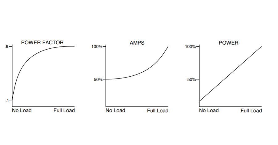
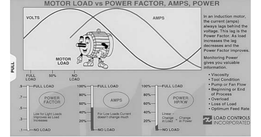
In an induction motor, the current ALWAYS lags the voltage. Power factor is the cosine of this angular lag. For a lightly loaded motor, the power factor can be as low as .1. You can think of this low power factor as electrical inefficiency. Current is flowing to the motor but it is not doing useful work (Power). As the load increases, the power factor improves and is typically .9 for a fully loaded motor.
Why Monitor Power Instead Of AMPS?
As you start to load a motor, the power factor improves rapidly. The current doesn’t change significantly until the motor reaches 50% of capacity.
- Power is linear. A change in load is a change in power (horsepower or kilowatts).
- It gives you the signal that you need for machine or process being monitoring and control.
- When the load is low, Power is low
- When the load is high, Power is high
- At light loads, Power is 10X more sensitive than amps
Mr. Motormouth Slide Rule and The Case of The Disappearing Amps
We often get calls saying, “I put a clamp-on ammeter on the motor and I’m getting 50% of full load amps. Your device is only reading 10%. What gives?”
If you look at the curve, you can see that for a lightly loaded motor, the current is high. Why? The power factor is low! As you start to load the motor, the power factor increases, but the current doesn’t change much. This is the advantage of sensing power rather than amps. When the load is low, the power is low. When the load is high, the power is high.
Mr. Motormouth is a cartoon character who says, “If your motor could talk, it would give you valuable information.” He has also put together a free slide rule that shows the relationship between motor load, power, power factor, and amps.
Let us know if you would like one.
Free Mr. Motormouth Slide Rule
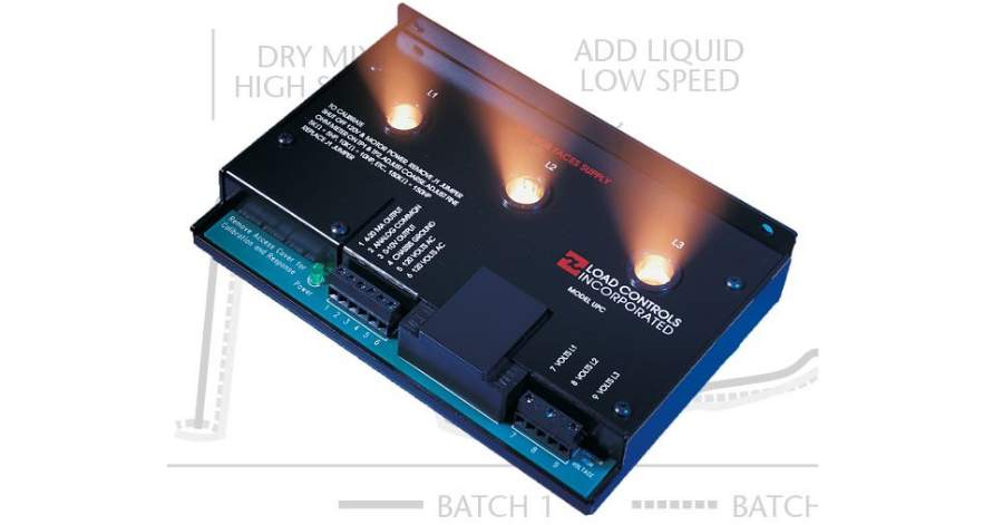
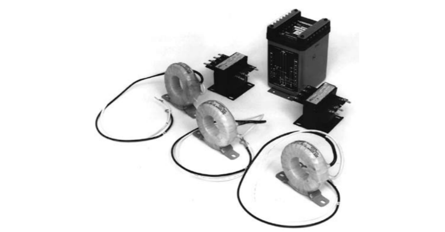
Two Ways To Measure Power
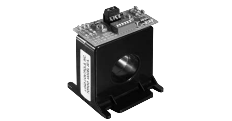
Power Cell
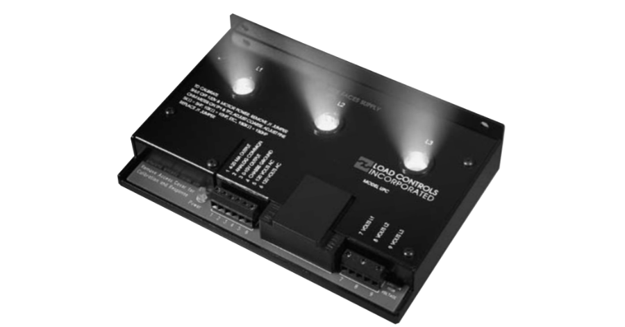
1.The Power Cell is a unique power sensor. It uses three balanced Hall Effect devices. Hall Effect semiconductors have these two characteristics:
- They sense a magnetic field. When a current-carrying conductor passes through a magnetic flux concentrator (donut) and the Hall Effect sensor is placed in a gap in the concentrator, the signal is proportional to the current.
- The Hall Effect semiconductor can multiply two signals. We excite the Hall Effect sensor with a signal that comes from the voltage sample for that phase. The Hall device multiplies these two signals.
The resulting output is then proportional to power (Volts x Amps). This is an instantaneous vector multiplication which also calculates the lag or lead of the current (Power Factor).
The signals for each of the three-phases is summed and the analog output signal is proportional to the threephase power (Horsepower or Kilowatts).
Using Hall Effect devices instead of the traditional current transformers and voltage transformers greatly simplifies installation. Accuracy is also improved by eliminating the phase shift errors from CT’s and PT’s which can be large at low power factors. The Hall devices will also work on the output of variable frequency drives.
The analog output can be hooked to meters, computers, programmable controllers, chart recorders and data loggers. It can also be used together with a “V” series load control if you want trip points and relay outputs.
Changing Capacity In Power Cells
The gain or amplification for each of the three Hall devices is set with resistors. In the newest version, the Universal Power Cell, the gain (which sets the value of the Full Scale capacity) is changed with a coarse and fine potentiometer adjustment. Put an ohmeter on two test points. The scale is conveniently arranged so that 5Kohms=5HP, 10Kohms=10HP, etc. So, if you set the Full Scale at 100Kohms (100HP) when the 4-20 milliamp scale reaches 20mA, 100HP is going to the motor.
In other Power Cells, Full Scale is set with plug-in calibrating resistor “networks.” These networks are in 8-pin packages that plug into IC sockets in the Power Cell and are field changeable. With any Power Cell, you can easily change capacity to match the load without the hassle of rewiring current transformers. This gives you maximum sensitivity.
Single Element Wattmeter
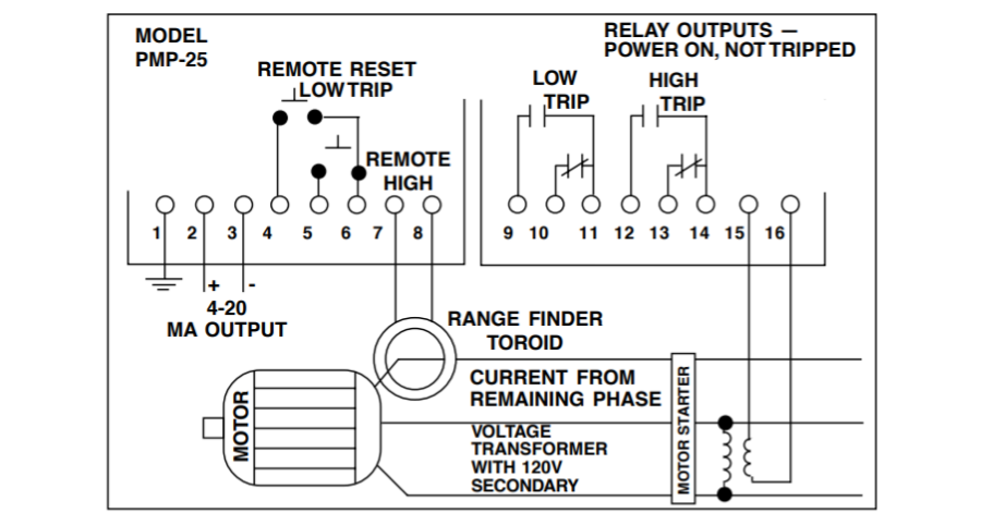
2. In many of our load controls, we use the single element wattmeter technique for sensing power.
Voltage
A 120-volt voltage signal is taken from two phases with a transformer. The assumption is: The 120 volt signal changes in the same ratio as the primary voltage. This 120-volt signal typically comes from a control transformer that is also used for other purposes.
Current
The current signal is taken from the REMAINING phase with a current sensing toroid that is either built into the control or located externally. For large motors, a current transformer is used together with the toroid.
The unique Range Finder Toroid has a dip switch capacity selector to simplify installation.
Power Factor
The control calculates the Power Factor by sensing the “zero crossing” of the AC voltage (AC voltage changes from + to – to +) and the zero crossing of the AC current. This lag is the Power Factor.
Assumption
The technique assumes that the load is balanced. Since a load control is normally used on a single motor, the imbalance between phases is small. If more than one motor is being sensed from a single location, use the Power Cell which measures current and voltage in all three phases. The single element wattmeter also doesn’t work well on variable frequency drives. If you are using a drive, you need to use a Power Cell.
Sensing Variable Frequency Power
Traditional techniques don’t work for measuring the power from a variable frequency drive.
- Current transformers (and clamp-on ammeters) don’t work at low frequency.
- Voltage transformers don’t work at low frequency.
- The wave shape as it leaves the drive is too distorted to use zero crossing techniques.
- Many lower-cost instruments are designed for sine wave calculations for values of current and voltage. Traditional schemes for measuring the power on the input to the drive are also not reliable.
- The drive doesn’t take its power in sine waves. It takes power only during part of the cycle as it is charging capacitors.
- The drive often takes power at a high power factor regardless of the motor load. This won’t give a true value for lightly loaded motors.
The solution is to use the Power Cell, since the Hall Effect sensors are not affected by the odd wave shapes and frequency. Also, no current transformers and voltage transformers are used.
These things don’t work on variable frequency drives.
Motor Load Controls
Motor load controls sense motor power and have builtin relays that trip when a set point is reached. Load controls have these features:
Set Points
The adjustable Set or “Trip” Points set the level at which the built-in relays will change state or “Trip.”
A load control can have 1, 2, or 3 Set Points, depending on the application. These Set Points can be:
High Trip – trips when the power goes above the Set Point
Low Trip – trips when the power goes below the Set Point
Relay Outputs
A relay works just like a switch. For example, it can be used to:
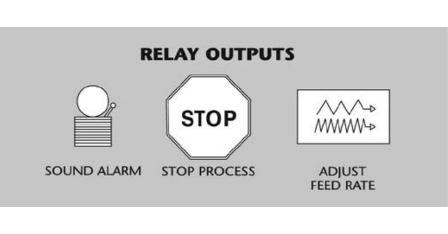
When the Set Point is reached the relay will switch (trip). Once it trips, it will latch in this position until it is reset (see RESET).
Analog Output
On all load controls there is an analog output that is proportional to the power that is being sensed. On most controls the output is 4-20 milliamps and the signal is powered by the control (no need for an external power supply). The analog output can be connected to remote load meters, chart recorders or can be sent to data acquisition systems.
When the Set Read switches on the Control are pressed, the analog output will show where the Set Point is. This makes set-up and adjustment easy.
Start-up Timer
When a motor starts, there is a large “inrush” of current. This can be 10 times as great as the normal running current. To avoid tripping the control during this period, an adjustable Start-up Timer bypasses the Control.
For convenience, the Start-up Timer senses the motor power and starts when the motor is turned on (not when the Control is turned on).
Trip Delay Timers
To avoid nuisance trips from short overloads (as a tool is entering the workpiece, for example), Trip Delay Timers bypass the Control for the selected time. The relays won’t trip until the time is exceeded. If the trip condition goes away before the time is up, the timer resets to zero.
Reset
When the relays trip, they will latch. The Control can be reset three ways.
- Manually with the Reset button on the Control
- Remotely with a remotely located Reset button
- Automatically by jumpering the Reset Terminal. The Control will then reset itself when the trip condition goes away.
The terminals for Reset generate a small amount of current (8-12 milliamps). To activate one of these functions you just need to connect the terminal to the circuit common with a jumper or a low current switch.
Response Time
The amount of time it takes a transducer to respond to a 90% of full-scale change in signal is the response time. Since we are measuring alternating current, the ripple must be filtered out of the signal.
This is usually a trade-off. Ripple-free signal usually means long response time (500 milliseconds). However, we’ve developed a unique multi-stage filter that combines fast response with clean signal.
For most load control applications, fast response is essential. For processing applications, such as
mixing and pumping, a slower or average response is preferable.
Power Cells ………………… Response Time = 15 milliseconds
Universal Power Cell …….. w/ Fast Response = 50 milliseconds
Universal Power Cell …….. Response Time = 500 milliseconds
Fast Response
Load Control ………………. Response Time = 25 milliseconds
Pump Load Controls …….. Response Time = 500 milliseconds
Overload Damage
The LCI Controls and Power Cells are designed so that they are NOT DAMAGED by overloads. At about 20% above full capacity, the internal circuitry just saturates. This prevents damage to attached meters, etc. It also means that the Control can be designed to match the running load without worrying about inrush current.


Comments