Author: Bob Latino CEO at Reliability Center, Inc.
Note to Series Readers. To those following this Series, I will apologize for the front-end redundancy. I am doing so for those that are NOT following the Series and will read these articles independent of each other. If you are following the series (Thank You!) and proceed past the front-end stuff and to the shaft pics below:-)
Abstract. In our last series highlighting the 4 primary Failure Modes (FM) of component failures (erosion, corrosion, fatigue and overload), we discussed how to read fractured surfaces. In this follow up series, we will take a look at tips on how to collect, preserve and examine such failed components.
I will reiterate my intent to make this series, as with the others, as basic and generic as possible. This will be old news, and metallurgy 101, to seasoned analysts. However, my outreach is to those on the front lines. You are the ones ones who will determine if the analysts get these failed parts or not, for a detailed root cause analysis. How the parts are preserved is extremely important to the investigators.
I will try to provide you enough education to make it challenging and fun, not only to properly preserve the failed parts, but to participate with your curiosity as to what influences, adversely impacted the failed parts?

Some of the basics in evidence preservation after a failure, include the following:
- Secure the failure scene. Rope off (caution tape) the scene and ensure it is safe for investigators to enter
- Take many pictures from many angles. This will preserve the scene in its ‘as-is’ state. Remember, at this point you may not know what is relevant to the failure itself, so ensure you take pictures of the entire failure scene. As you collect the facts and analyze them, things in your initial pictures will make more sense.
- Clear close-ups of failed areas. Take high resolution pictures of the failure scene and especially the failed surfaces of broken components. These pictures will likely be blown up to look for more granularity. Such pictures will include the following (in this article) but are certainly not limited to them:
- Sight glasses – ensure you take pictures at the angles in which someone would be viewing the sight glass (sometimes sight glasses can be easily mis-read due to parallax error [the angle at which they are viewed])
- Piping – note if the failures occur at ‘T’s’, ‘U’s’ or straight runs. If cracks, are they parallel or perpendicular to the pipe run? Is the failure at a weld?
- Valve positions – note valve positions as on, off or partial open
- Structure – base etc. – note any anomalies in structures which could contribute to the failure (i.e. – resonance, soft foot, etc.)
- Couplings – note all anomalies on the coupling (just like we will described here for roller bearings)
- Guards – note the condition and location of guards (even if they exist at all).
4. Take pictures up & down stream of failure. Initially, we may not know if there were upstream and/or downstream influences that contributed to the failure. Therefore we must preserve those scenes as well.
5. Take video of failure event area. Chances are you will be time-pressured by production to hurry up and get what you need and then get out, as they will want to get production rolling again. Fastest way to preserve the scene is with video!
6. Map out the event scene as needed. Once you have your pictures and videos, draw a map or sketch of the failure scene and note where the anomalies are the located. This will be a team job aide in the investigation.
7. Interview key people who were present as the event unfolded. It is extremely important to interview witnesses immediately. The longer you wait to interview, the more attention to detail you will lose (due to short-term memory loss). You will also lose direct observation information if the witness is influenced by talking to others involved (say in the break room), and their opinions are reshaped as a result.
8. Map out where each person was during the event. Just like we talked about mapping out physical anomalies at the failure scene, we should also note where key players were as the failure unfolded (as opposed to where they should have been).
9. Create a timeline. An accurate and detailed timeline of events leading up to the failure is always critical to the investigation.
10. Leave instructions with area leadership about what parts you want & where to stage them. You may not be able to get certain parts you need because they are still in operation. If this happens, you will need to get cooperation of area leadership to ensure you get the parts when they are available (perhaps a shutdown). This will require some planning about where you want them to stage the desired parts.
In the following clips, you will notice there is some redundancy in the guidance on each clip. This is because it is anticipated that if this article is printed off, each clip will stand independent of the others.
SHAFT INSPECTIONS
Since this article is focusing only on Shafts, we will provide basic guidance of how to preserve, document and examine the evidence in an unbiased manner.
Once the failed/damaged shafts are preserved we need to consider the following tasks to help us properly document our inspection into our evidence logs.
- Before doing the inspection obtain the drawings and specifications of the shaft
- Use micrometers to measure the shaft and compare the measurements to the specifications (include radius measurements)
- Perform hardness testing to various places on the shaft like bearing seats and compare to the specifications
- If you have access to a nuclear alloy analyzer, use it to establish the shaft material and compare to the specifications
- Use laser alignment tools to check for any irregularities like a bent shaft.
When inspecting a shaft it is important to take measurements to identify the specific location of anomalies and where on the rotation of the shaft they appear. Note any degradation to the diameter of the shaft, and where it is located. Compare this to the specifications. Any ‘gaps’ will have to be explained during the course of the RCA.

Looks for any signs of rust (or oxidation) and note its location. The RCA will have to explain how the shaft was exposed to moisture and oxygen, in order to permit rust to form.

In these pictures below we are noting the location of ‘peen marks’. It is important to note where the peen marks are located on the diameter of the shaft. If you are not familiar with ‘peening’ and its purpose, here is a basic explanation about “What is Peening?”
Peening is a cold-working process in which the surface of the component is deliberately deformed, in the basic method, by hammering. It expands the surface of the cold metal, thereby inducing compressive stresses or relieving tensile stresses already present. Peening can also encourage strain hardening of the surface metal.
During peening, the surface layer attempts to expand laterally but is prevented from doing so by the elastic nature of the sub-surface, bulk material. This results in the development of beneficial, compressive residual stresses in the surface layer, which are balanced by tensile residual stresses elsewhere. The layer of compressed surface material produced by peening resists the development and propagation of cracks and increases resistance to fatigue failure, corrosion fatigue, stress corrosion and cavitation erosion.
The most common peening techniques are:
Shot peening – Involves bombardment of the metal surface by spherical shot. The shot consists of rounded particles of cast iron, cast steel or stainless steel in various mesh sizes. Both mechanized and manual systems are used, depending on the particular component and area to be treated.
Roto (flail) peening – The surfaces are impacted by two or more shot-coated flaps which extend radially from a spindle. Each flap consists of shot (cast steel or tungsten carbide) embedded into a wire mesh or fiber.
Needle peening – Uses a de-scaling gun but with needles having ‘radiussed’ ends. The cluster of metal needles is usually made from hardened tool steel.
Hammer peening – Similar to needle peening except that a single metal rod, rather than a cluster of needles, is used and applied in a similar way.
Source: https://www.corrosionpedia.com/definition/864/peening
In this picture we note the location of the initial peen marks (they look like dimples on a golf ball).

On this picture we note there are also peen mark’s, 180 degrees opposite of the other noted peen marks. The RCA will have to explain this, but oftentimes this is evidence the shaft was put into a vice.

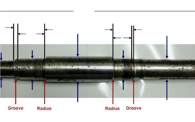
In the picture below we are noting the presence of any grooves that have formed, and their locations. We will again compare against the specs and determine the ‘gaps’. You will also notice horizontal ‘chatter’ marks. Both of these anomalies will have to be explained by the RCA. With regards to the ‘chatter’ marks, this is often a sign of the frequent replacement of bearings (slide marks going in and out).

On this last picture below, we observe fretting corrosion. If you will remember from our past article on general corrosion, fretting is often associated with improper fits. The location should be noted, compared to the specs and accounted for in the RCA.
This will end our basic tips on how to preserve, document and examine shafts to prep for an RCA. I will likely post similar articles in the future, but on different components. However, the handling of them will all mirror what I described in this article.
Just as an FYI, I am pulling all of this material from public workshops we offer, taught by practitioners and not just trainers! These workshops range from the very basic to those who really want to get into this fascinating field of metallurgical analysis and Root Cause Analysis (RCA), and become Lead Investigators.
As always, I appreciate all of the great feedback and the sharing from the veterans in the field…the front-lines who make things happen!! Thank you for your time and participation.
Learn more about Why Parts Fail.


Hi, I liked this article and I’d like to recommend the reading of the entire series to the Reliability Engineers in my organization. Please can you let me know what other articles belong to this same series so I can send them all the links?
You can find more article from RCI here: http://test.empoweringpumps.com/blog/category/company-articles/reliabilitycenter/ , and I will connect you and Bob via email. Thank you for sharing the articles with your team ~ Charli
Hi Luiz
You can find more articles like this at https://www.reliability.com/rcafix/ where we have a dozen or so of those types of articles.
Also you can go https://www.reliability.com/reliability-movies.htmlpage to see many video case studies.
If you have any questions, just let me know. We have worked with Dow in the past and welcome the opportunity to assist in the future as well.
Bob Latino