Authors: Garrett Abbott-Frey, US Process Drive Offer Manager – Industry Business, Schneider Electric, and Jack Creamer, Market Segment Manager, Pumping Equipment – Industry Business, Schneider Electric
The promise of new technology to combat an age-old challenge, like harmonics, is very appealing. However, the introduction of this technology leaves many with questions:
- What is this new solution?
- What features and Drive characteristics are needed to deem the product as useful?
- How does this new 3-Level Active Front End drive technology solves my problems?
- Will it work with other critical components, like generators?
This article will answer these questions and explain the operational benefits that these 3 Level Active Front End drives brings to the table. From the small footprint, to an overall high performance when compared to other mitigation solutions. The 3-level design is the solution to mitigate your harmonics and to improve your processes performance and efficiencies.
Performance
Figure 1 shows the measurements of the mains current of a 160 kW drive with an active input rectifier. The drive is operated at a 400 V mains with 50 Hz mains frequency and at nominal power (Pnom = 160 kW). In Figure 1(A), the drive is operated in motor mode, where the energy flows from the utility grid to the motor. In Figure 1(B), the drive is operated in regenerative mode, where the motor feeds energy into the utility grid.
The currents are nearly sinusoidal and in phase with the mains voltage (only mains voltage of phase L1 is shown). In both cases, the measured THDi of the mains currents is around 2%. However, the feeding voltage already shows a THDv of approximately 2%. The THDi of the mains current is primarily determined by the voltage distortion of the power distribution system. B
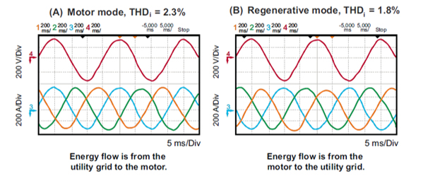
Figure 1: Measured Mains Current
Measured mains current of a 160 kW drive operating at nominal power (V = 400 V, f = 50 Hz, P = 160 kW). The feeding voltage already shows a THD of 2%.
In addition to measuring input current distortion, the efficiency of Schneider Electric’s low harmonic solution was measured. The result was a high efficiency value of 96.5% for the entire drive at nominal load in motor mode. This high value is primarily due to the reduced switching losses of the three-level topology, the optimized DC bus voltage, and the lossless damping of the optimized LCL input filter.
Generator Testing
Schneider Electric tested an ATV980C31T4N2GNWABN regenerative process drive using an 800 kW diesel generator. Table 1 compares the effectiveness of Schneider Electric’s low harmonic drive solution to other solutions with respect to harmonic mitigation. Figures 2 through 7 provide an overview of the testing performed.
NOTE: The measured harmonics for Schneider Electric’s Altivar 680 low harmonic drive would be the same as those for the Altivar 980 regenerative process drive, since both drives have the same input bridge design.
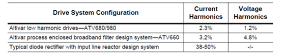 Table 1. Harmonic Levels as Measured at the Input Drive Terminals
Figure 2: Input Current of ATV680/980 Low Harmonic Drives. Note the sinusoidal wave shape and balanced currents.
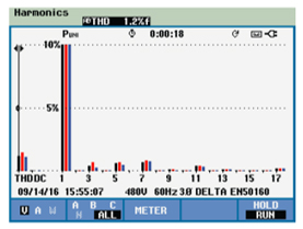
Figure 3: Input Voltage Harmonics of ATV680/980 Low Harmonic Drives. THDv is 1.2% of the fundamental (60 Hz) component.
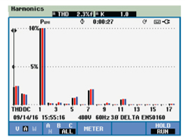
Figure 4: Input Current Harmonics of ATV680/980 Low Harmonic Drives. THDv is 2.3% of the fundamental (60 Hz) component.
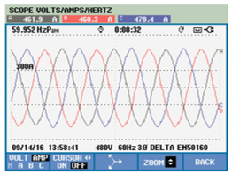
Figure 5: Input Current Waveform of an ATV660 Enclosed Broadband Filter Design System. Current waveform is generally sinusoidal but you can see some additional bumps in the waveform.
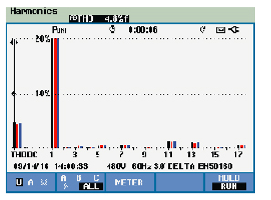
Figure 6: Input Voltage Harmonics of an ATV660 Enclosed Broadband Filter Design System. THDv is 4.8% of the fundamental (60 Hz) component.
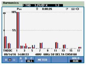
Figure 7: Input Current Harmonics of an ATV660 Enclosed Broadband Filter Design System. THDi is 3.2% of the fundamental (60 Hz) component. This is well below the required 5%, but not as optimal when compared to Schneider Electric’s ATV680 and ATV980 low harmonic drive solutions.

Figure 8: Input Current Waveform of a Standard Drive with an Input Line Reactor Design System
As a comparison for when harmonic mitigation is not used, this is the input current waveform for a system similar to that in Figure 7, but using only an input line reactor.
This is the typical current waveform that occurs with a standard drive containing a 3% line reactor or equivalent DC choke. The harmonic content can range from 38% to over 50%.
Harmonic Performance at Various Loads
To determine how the low harmonic drive solution performs when the drive is not fully loaded, testing was conducted to better understand its performance. Figure 9 shows the relationship between partial load and harmonic levels for a large, low-harmonic drive solution.
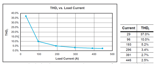
Figure 9: Schneider Electric’s Low Harmonic Drive Solutions Harmonic Performance at Partial Loads
As the load current drops from 446 A down to 193 A (43%), the THDi increases gradually from 2.5% up to 5.2%. Even at 96 A (21% load), the THDi is only 10%.
Prospective Short-Circuit Current
Schneider Electric’s low harmonic drive solution will work on a wide range of power systems. The maximum prospective short-circuit current is 100 kA. The minimum recommended prospective short-circuit current is 3 kA on the smallest size drive and 17 kA on the largest size drive.
Input Filter
The pulse width modulation from the input is filtered by an LCL filter. This PWM operates at 7 kHz, so it is easier to filter it out than it is with active rectification drives which use a 4 kHz or lower switching frequency.
Filters with multiple components can resonate at certain frequencies, so a method of damping out the oscillations is needed. Two-level designs use resistors to dampen the circuit, but this can waste power. Schneider Electric’s low harmonic drive solution has an improved method of actively dampening the circuit, eliminating the additional components and losses associated with the resistors.
Input Power Factor
Input line reactors can lower the power factor. Other technologies such as broadband filters have high capacitance so they can have a leading power factor at lighter loads. To prevent leading power factor at low loads, Schneider Electric adds a contactor to disconnect the capacitors until the drive is up to a certain load. By contrast, the low harmonic drive maintains a near unity (1.0) power factor over a wide range of loads.
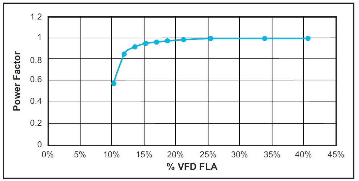 Figure 10: Input Power Factor of Schneider Electric’s Low Harmonic Drive Solution at Partial Loads
From Schneider Electric’s generator testing, it can be seen that the power factor stays near unity down to very low levels. A unity power factor has the lowest current level for a given amount of power, so this can reduce the demand current on the system. While any specific generator should be evaluated for operation with a VFD, most are rated to operate properly with unity power factor. In addition, for generator use, the four-quadrant regenerative capability can be turned off to reduce the risk of back-feeding the generator.
Conclusion
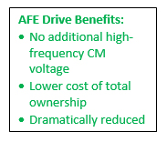
With this technology, it is now possible to replace a passive diode bridge rectifier with a low-harmonic input stage or a regenerative input stage. Benefits include no additional high-frequency CM voltage, lower cost of total ownership, and dramatically reduced harmonics.
One of the most beneficial elements these low harmonic drives deliver are lower bearing currents when compared to simple two-level active front end drives. This industry-leading, three-level active rectification design results in lower output bearing currents, similar to those found with typical 6-pulse drive systems. These reduced bearing currents extend the service life of the motor bearings therefore lowering overall operating costs.
 Due to the optimized LCL input filter, high-frequency emissions caused by the switching actions of the active bridge are well attenuated to values below 0.5%. The possible resonance of the input filter is damped by an innovative lossless active damping control strategy implemented in the controller of the low harmonic drive system. The resonant tank built by the filter elements cannot be excited by the utility grid. This optimized input filter allows the 3-Level Active Front End Drives to have a 40-50% reduced footprint when compared to 18 pulse solutions.
Leveraging three-level topology, lossless damping of the input filter, and optimized DC bus voltage, this low harmonic solution exhibits very high efficiency. The Altivar 680 and 980 low harmonic drive systems improve reliability and efficiency in generator applications by maintaining a power factor near unity down to 20% of VFD rated full load amps. This high efficiency, combined with the high input current quality, small size, and significant reduction of high-frequency CM voltage caused by the active bridge, make this three-level low harmonic offer a smart technology selection for a drive system with low harmonic requirements – with or without power line, regenerative capabilities – for any industry or application that requires a compact, low harmonic solution.
Thus, begins a new chapter in power conversion devices.
This article is part of a five-part series looking at new technologies in harmonic mitigation – including the industry’s first three-level low-harmonic drive – designed to uniquely address the harmonics issue. For more information, please visit: goo.gl/zFuMXf.
About the Authors
Garrett Abbott-Frey is the U.S. Process Drive Offer Manager in the Industry Business of Schneider Electric. Based in Raleigh, North Carolina, Garrett brings nearly 5 years of professional experience to the role drawing from previous positions in OEM Machine Design and Electric Motor and Drives validation and testing. He currently focuses on Enclosed Drive Systems targeting the upstream Oil & Gas industry to support production process optimization for customer Artificial Lift applications. Garrett has led numerous training sessions on harmonics, drives commissioning, and other drives-related topics as well as recently publishing the whitepaper, “Transformation from Six-Pulse to Low Harmonic, Three-Level, Active Rectification Technologies.” He has a bachelor’s in Mechanical Engineering from North Carolina State University with a focus on Physics and Environmental Science.
Jack Creamer is Schneider Electric Segment Marketing Manager – Pumping Equipment, based in the United States. Mr. Creamer has more than 30 years in the Electrical Industry, and has been involved for 10 years in the Pumping Industry. He is involved in key industry organizations such as the Hydraulic Institute and Submersible Wastewater Pump Association, where he holds both Committee Chair and Board level positions. In his time in the Pump industry, he has help Schneider create numerous solutions that both enhance pumping efficiency and address issues such as maintenance and downtime.


Comments