
Author: Heinz P. Bloch, P.E.
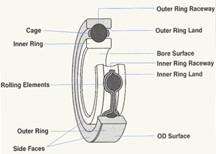
Figure 2
Visualize the oil level in a bearing housing reaching just over the side face at a bearing outer ring land near the 6-o’clock position (see Figure 1). Now visualize the oil level going down by a very small distance because of windage, or due to non-equal pressures on the two bearing faces. Suddenly, the oil level no longer reaches the outer ring land. No more oil will now reach the rolling elements and the top layer of oil will overheat and turn black.
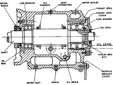
Figure 3: A 1960s Worthington Pump bearing housing with pressure equalization passages
Black oil, then, can sometimes be traced to a particular bearing cage geometry, or omission of an equalization passage. It’s interesting to note that Worthington, in the 1960s, drilled pressure equalization passages in their pump bearing housings (Figure 3). Without these passages, oil entrainment on the higher pressure side will create fluid movement towards the lower pressure side, just as the laws of physics predict and explain. Because all kinds of variables come into play, among them shaft speed, bearing configuration, bearing protector seal geometry, oil characteristics, lube application method, bearing housing size , lube level and others. Your pump manufacturer rightly points out that plants “X” and “Y” have the same pump as you and there are no complaints from either location. That may be very true, but your variables interact differently. Insistence on equalization of pressures in front and behind bearings addresses the root issue. Talk is a diversionary tactic at best.
Today, pressure equalization passages are of even greater importance than years ago. Today, we use bearing housing protector seals that allow (and sometimes even promote) slightly different pressures. So, again: Unless the pressures on both sides of a bearing are equal, you are at risk of oil-related issues. Perhaps you have experienced “black oil.” Black oil in pump bearing housings is either overheated oil or lubricant contaminated by O-ring debris. The reason for oil discoloration must be identified before the proper remedial action can be planned. Opting for just an oil change will not address the root cause of lubricant degradation or discoloration. It will likely result in a repeat failure.
Radial vs. axial (thrust) bearings
Pumps designed and marketed in the United States generally use deep-row radial ball bearings near the impeller and back-to-back mounted angular contact bearings on the thrust side. The thrust side is near the coupling. European pump designs generally favor higher load-rated cylindrical roller bearings near the impeller. Higher initial cost and the need to use greater care come into play.
API-610 requires brass for the bearing cage. It’s difficult to determine why brass cages are mandated years ago. If there is skidding in a bearing, brass is not ideal; it will smear. It’s also much heavier than high-performance plastic cages. Perhaps certain polymeric cage materials deformed and softened when bearings were heated to excessive temperatures during shop assembly.
Since a good procedure calls for pressing the bearing on the shaft with interference fits ranging from 0.0003 to 0.0007 inches, the issue should be moot. Japanese refineries don’t seem to have the brass and smearing problem. They use bearings with high-performance polymer cages and ascertain the shaft interference fit is correct. Japanese users recognize that certain bearing-related clauses in API-610 are a concession to tradition. Certain bearing-related clauses have not kept pace with knowledge Some refineries routinely reach average pump MTBFs (Mean Time Between Failures) of 9 years while others are happy to reach a below average MTBF of only 3 years. Which proves that “Knowledge is Uptime.”
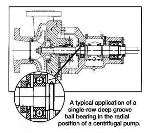
Fig. 4: API 610 style centrifugal pump cross-section with radial bearing circled
Regardless of bearing style, the bearing in the radial location should be free to move axially, whereas the outer rings of a thrust bearing assembly should be restrained in place. However, applying an excessive clamping force would risk distorting or buckling the outer ring. Allowing the thrust bearing set to axially move as much as 0.002 in (0.05 mm) ensures there is no unduly large clamping force. Allowing it to move more than 0.002 may invite it to slam back-and-forth during recirculation or cavitation events. This can wreck the bearing; the force acting on the bearing will be F=ma. Here, “m” is the mass of the rotor, “a” is the acceleration, essentially dv/dt (the change of velocity during force reversals with respect to time). It’s a big number and it’s (again) physics at work. Remember: It’s foolish to deny the applicability of these laws. Only the Creator himself can change them, and if he does, we’re in big, BIG, big trouble.
Although called thrust bearing, bearings at the thrust location in pumps are generally absorbing loads in both the axial and radial directions. A double-row thrust bearing is shown in the API pump (Figure 4) and the ANSI (standardized dimension) process pump of Fig. 5. The thrust bearing in this illustration is a double-row angular contact bearing (DRACB) with a single inner ring. A double-row bearing with two separate inner ring halves is available for applications where somewhat higher loads must be accommodated. A castellated (cog-type) clamping nut and tab washer are required to secure bearings with two inner rings to the shaft.
ANSI pump bearings are generally inferior to the bearings found in API pumps. Regardless of pump specification, when bearings fail the root cause of such failures is rarely an undersized bearing. Very often you’re dealing with oil contamination, flawed installation, and piping being pulled into place. If you allow piping to be pulled into place, you will often cause the bearing to become edge-loaded. The rolling elements move away from their ideal paths and contact the edge of either the outer ring or inner ring (see Figure 2) raceway. Remember that a bearing ball exerting a force of 10 lbs on an area of 0.01 square inches causes the resulting pressure of 10/0.01=1,000 psi. That’s perfectly acceptable when you have a good oil separate the metals. If, on the other hand, the same 10 lbs force acts on a sharp edge and that edge has a contact area of 0.0001 square inches, the resulting pressure will be 10/0.0001= 100,000 psi. Now there will be metal-to-metal contact and the bearing will fail almost immediately. Yep, bearings obey the laws of physics and punish those who assume that piping can be pulled into place with total impunity. “Knowledge is Uptime.” A disregard of physics equals downtime—always.
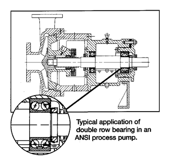
Fig. 5: ANSI style centrifugal pump cross-section with double-row thrust bearing circled. Note castellated nut and tab washer
A castellated clamping nut must be tightened with a special spanner wrench; regrettably, this wrench is not usually found in the average machine shop. Some mechanics tends to use a chisel, which inevitably causes damage to the equidistant cogs (“castellations”) in the periphery of the nut. Anyway, a proper spanner wrench must be used and the tab washer discarded after each disassembly. Re-bending a tab would weaken it to the point of risking low cycle fatigue failure. You can do this stuff to the bearings of a skateboard, but please don’t do it on a process pump.
In special double-row two-piece inner ring bearings (rarely used), each inner half incorporates its own land and raceway, but the overall external dimensions are identical to those of a DRACB with the single-piece inner ring shown in Figure 5. The inner rings of these special ANSI thrust bearings are clamped to the shaft and the outer ring is restrained in its housing bore position. Again, the clamping force should be very light so as not to distort the bearing outer ring. Alternatively and to simply ascertain that the clamping force is not excessive, one might allow an outer ring axial movement of up to 0.002 inches (0.05 mm) relative to the bearing housing bore.
References
- Bloch, Heinz P. and Allan Budris; “Pump User’s Handbook: Life Extension,” 4th Edition, (2014), Fairmont Publishing, Lilburn, GA, ISBN 0-88173-720-8
- Bloch, Heinz P.; “Pump Wisdom: Problem Solving for Operators and Specialists”; (2011), Wiley & Sons, Hoboken, NJ; ISBN 9-781118-04123-9
- Bloch, Heinz P.; “Petrochemical Machinery Insights,” (2016) Elsevier Publishing, Oxford, UK, and Cambridge, MA, ISBN 978-0-12-809272-9


Comments