Contributor: Applied Flow Technology
When completing the analysis on a model, there is nothing more frustrating than having to do the same thing over and over again. Thankfully, using AFT’s Piping Layout Wizard you will no longer need to rebuild your CAD, CAESAR II, and EPANET files to analyze the hydraulics using AFT Fathom 10, AFT Arrow 7, and AFT Impulse 7. In addition to GIS shp files, our updated import features can now bring in the piping layout and basic information from .pcf, .cii, and .inp type files. Let’s take a look at how quick this process can be with a basic pcf file import.
Overview
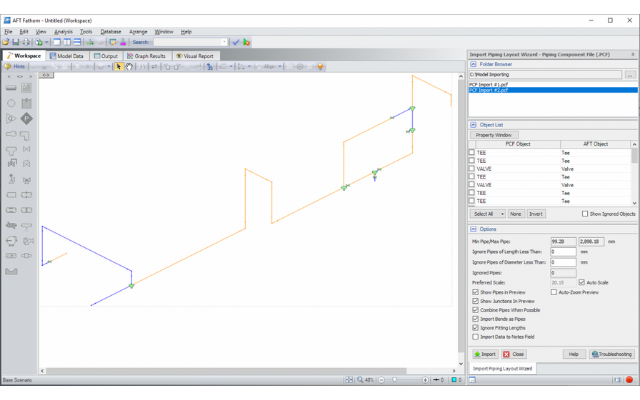
To start, choose your file type from the import menu, and browse to the file layout. The Import Piping Layout Wizard will show a preview of the file, which makes it easy to find the correct model, as can be seen in Figure 1.
Note that AFT Fathom the Piping Layout Wizard will automatically scale the model to fit in the workspace and will automatically zoom the preview to fit the window, allowing for better management of large models.
Now that we have selected the model, there are several things we can do to update the model before importing, including changing the junction types, removing unnecessary junctions and pipes, and changing the way the pipes/junctions will combine.
Object type
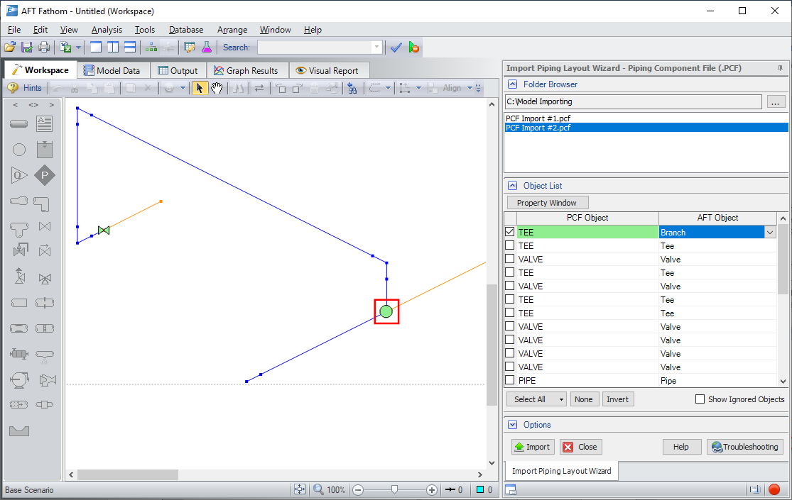
Figure 2: Changing a Tee PCF Object in the Object List to a Branch Junction using the Import Piping Layout Wizard
The Layout Wizard will automatically read the object type in the PCF file and choose a corresponding junction type in AFT. Using the preview in the Workspace, the current import settings can be easily visualized to make the process intuitive. The object list allows you to change the identified junctions quickly before import, rather than morphing individual junctions after the import has occurred. Simply select the desired junction in the Workspace to highlight it in the Object List, then set a new AFT Object, as shown in Figure 2.
In addition to changing junction types, extra items can be set to not import by choosing “none”. For example, we may be interested in modelling the valve pointed out in Figure 3 as a closed valve, in which case it would be useful to remove the extra pipe downstream of the valve by setting the object type to “none”.
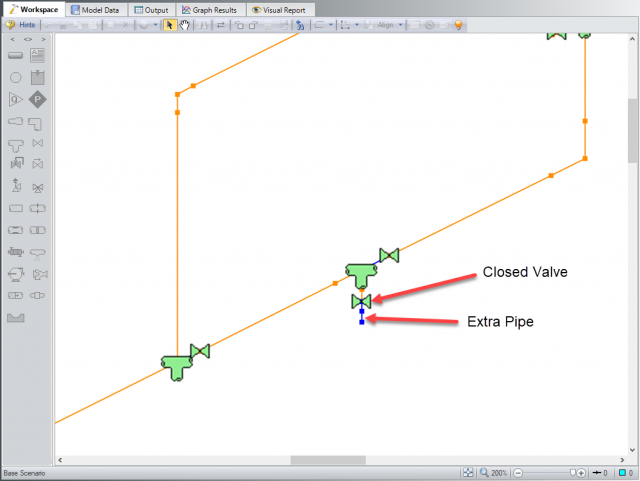
Figure 3: Extra pipe to be removed
The property window button can display simple parameters such as elevation, length and diameter that will be imported for the object to more easily identify them.
For CAESAR II Neutral files extra information is available such as wall thickness, temperature and pressure information associated with the element being brought in.
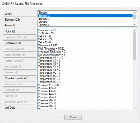
Figure 4: Additional information available when importing Caesar II neutral files
Options
Once the junctions and pipes have been set up by object, the Options section can be used to fine tune the model to be setup for hydraulic analysis. Pipe layouts coming from other software often contain details and components which are not necessary for the calculations done in AFT Fathom, AFT Arrow and AFT Impulse. A few examples are jacketing on pipes, which are represented using heat transfer settings in AFT Fathom or AFT Arrow, or small connecting fittings which are better represented using Pipe Fittings & Losses entered in the Pipe Properties window.
Ignoring pipes of small diameters or very short lengths can help to exclude these in bulk, rather than removing them individually. There are also alternative options such as combining adjacent pipes and ignoring fitting lengths which help to optimize the model input for hydraulic analysis by reducing the number of pipe and junction objects. Generally leaving these options turned on is recommended, since this requires less data to be brought in and speeds up the import process.
A Few Extra Tips
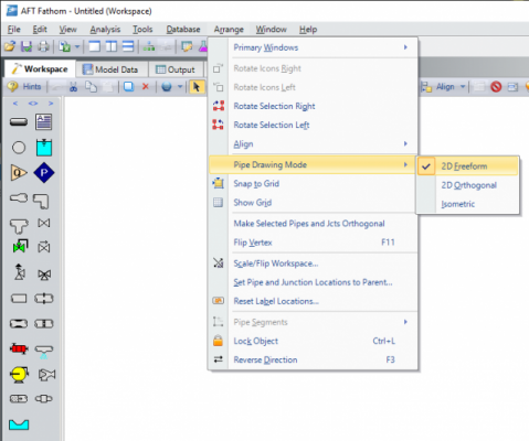
Figure 5: Setting the Pipe Drawing Mode and grid settings in the Arrange menu
Before opening the piping wizard, make sure that the Pipe Drawing Mode is set to 2D Freeform from the Arrange menu, and that “Snap to Grid” is disabled as shown in Figure 5. This allows the junctions and pipes to import directly as shown in the preview. When the AFT 2D Orthogonal and Isometric grids are enabled they do not always line up well with imported layouts due to differences in grid sizing.
After importing a pcf or CAESAR II file it should be noted that additional files can be imported if desired, unlike previous versions of AFT Fathom, AFT Arrow, and AFT Impulse. This allows for large systems to be imported in multiple, more manageable sections. Simply browse to another file name at the top of the Import Piping Layout Wizard as shown in Figure 6.
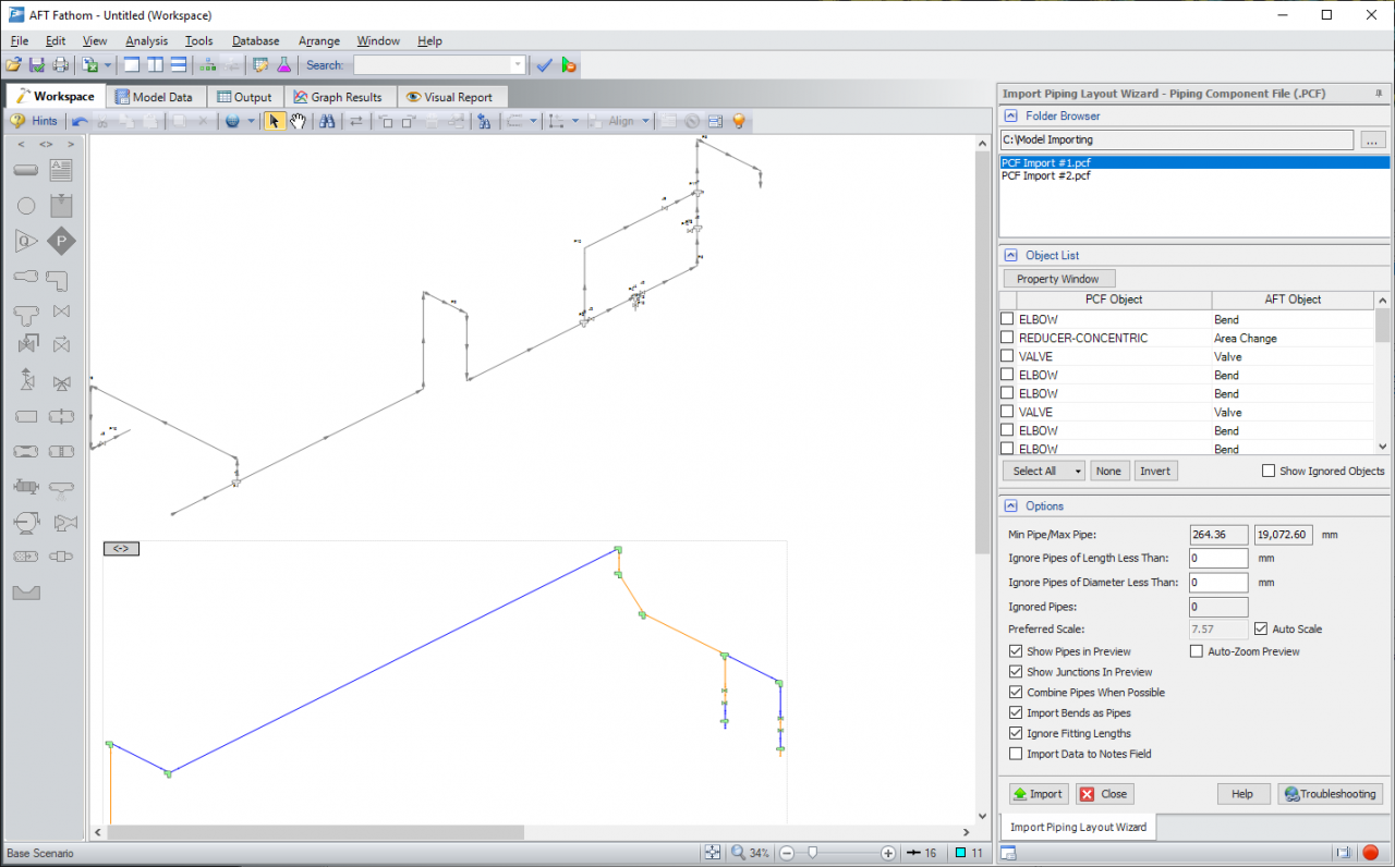
Figure 6: Multiple pcf files can be imported into the same workspace at once using the Piping Layout Wizard
Overall, importing with AFT’s Import Piping Layout Wizard provides a large amount of flexibility to the user to control exactly what data they need for analysis in order to speed up the import process, and overall speed up the hydraulic analysis.


Comments