
Author: Jeff Sines, Engineered Software Inc.
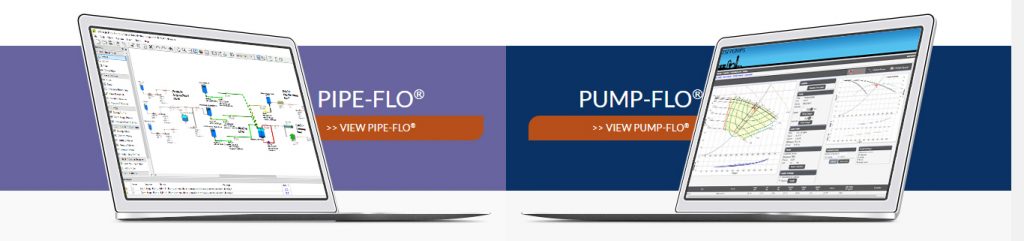
There are several ways to model a sprinkler system or a system with nozzles in PIPE-FLO® Professional.
Sprinklers, fire suppression nozzles, and spray nozzles are typically characterized by a Discharge Coefficient which some nozzle manufacturers represent with the letter K, used in the following equation:
|
Q=KdP−−−√Q=KdP
|
This conflicts with the way PIPE-FLO® uses the letter K, which is used to represent the Resistance Coefficient of valves and fittings. This inconsistent use of nomenclature has resulted in confusion when modeling a spray nozzle within PIPE-FLO®. For a spray nozzle, increasing the value of the discharge coefficient increases the flow rate through the nozzle, but when using the resistance coefficient to describe a spray nozzle, increasing the resistant coefficient decreases the flow rate through the nozzle.
The nozzle discharge coefficient is also equivalent to the flow coefficient (Cv) when used with water at 60°F (SG=1.0), using U.S. units (N1=1.0), and no piping fittings (Fp=1.0), as shown in the following equation for Cv for a control valve:
|
Cv=QN1FPdPSG−−−√=KnozzleCv=QN1FPdPSG=Knozzle
|
When using the Darcy Weisbach calculation method, the nozzle can be modeled as a:
1. Curve dP Device
2. Fixed Cv
3. Equivalent fixed resistance (K) fitting in a pipeline
When using the Hazen Williams calculation method, the nozzle should be modeled as a component with a curve. The fixed Cv and fixed resistance cannot be used because dP is calculated using Q2 for these methods, whereas Hazen Williams uses Q1.85 to calculate the head loss and dP.
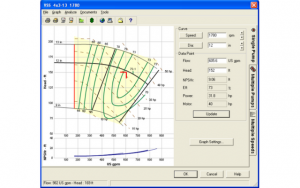
Consider the following graph given by a nozzle manufacturer for a range of available nozzles:

Nozzle as a Curve dP Device (Darcy or Hazen-Williams Method)
To model the nozzle as a component with a Knozzle= 7.2, several data points can be generated for the curve data dialog box data table using the nozzle equation, Q=K(dP)0.5. This is easiest done in Excel as shown below.

The data points can also be read from the manufacturer’s graph.
The spray nozzle is modeled with a Curve dP Device  , a small pipeline, and a Pressure Boundary Device
  . These devices are shown below.

Next you add the spray nozzle curve data to the Curve dP Device. This is done by selecting the Curve dP Device, right clicking the mouse, and selecting “Enter Curve Data”. A Curve Data dialog box, like the one shown below, will appear. Enter the flow rate and dP data into the corresponding fields.
 The small pipe connecting the Curve dP Device to the Pressure Boundary Device has a very short length (0.001 ft) and the same size as the upstream pipe . Next set the Pressure Boundary Device to 0 psig. PIPE-FLO will use the Curve dP Device curve to determine the dP for the calculated flow rate. Shown below is a spray nozzle being modeled as a Curve dP Device and a Pressure Boundary Device. The calculated dP can be compared to the manufacturer’s graph at 45 gpm.

Nozzle as a Fixed Cv (Darcy Method ONLY)
The nozzle can also be modeled as a fixed Cv installed as a fitting in a pipeline of very short length, as shown below. Installation of the fixed Cv is done through the pipeline’s Property Grid.
 Again, as the flow rate changes, the correct differential pressure will be calculated, as shown below and confirmed in the manufacturer’s graph above. Conversely, as the inlet pressure of the nozzle changes, the correct flow rate will be calculated.

Nozzle as a Fixed K (resistance) (Darcy Method ONLY)
Modeling the nozzle as a fixed resistance (K) requires the use of the differential pressure dynamic equation, dp = K (Densityfluid/144)(v2/2g), rearranging to solve for K.In this case both the flow rate and pressure are taken from the manufacturer’s graph where flow rate and pressure are 50.9 gpm and 50.04 psig respectively. Note that in this example the inside diameter of the pipe is 6 inches and velocity is derived from the continuity equation with units of ft/sec. This yields a resistance coefficient of K=23266.
 The use of the fixed K can be confirmed by comparing another point on the manufacturer’s curve, in this case at 55 gpm, PIPE-FLO calculates a dP of 58.38 psi. This corresponds to the value on the graph.

Modeling a Fire Suppression System
Modeling nozzles as components can be seen in the following fire suppression system in which PIPE-FLO® is used to size the fire pump to ensure at least 20 gpm at each nozzle (discharge coefficient = 3.2 from the manufacturer’s graph above). Each nozzle is modeled as a component using calculated data points from the nozzle equation. The Darcy calculation method is used. The figure below shows a scenario in which the entire system is activated on both floors. The pump was selected based on a design point of 500 gpm and 110 ft of head.

Below is the same system except that the nozzles are modeled as fixed Cv fittings in the pipeline. Flow rates are comparable to the system above, with the exception of a slight variation due to the linear interpolation method used in the components above.

Here is the same system using components to model the nozzles and using the Hazen-Williams method to calculate the head loss. In this situation the flow rates and dP are comparable to the two models above, but this is highly dependent on the Hazen-Williams “C” factor, the pipe sizes, and the use of water at 60°F.

See All Content from Engineered Software Inc.!
http://test.empoweringpumps.com/products/engineered-software-pipe-flo-professional-fluid-flow-analysis-software/


Really happy to say, very interesting to read your post to fire Sprinkler Modeling. I will never stop myself from saying anything about this. You are doing a great job. Keep going.